
Table of contents: Removal ↓ Installation ↓
Attention! The procedure is given using the example of cars with a diesel engine.
Removal
1. Remove all available fuel from the tank if it has not been used up. In workshops, a special fuel extraction device VAS 5190 is used for this purpose (see illustration 3.1).
2. Remove the rear seat.
3. Unscrew the bolts (see arrows in the illustration) fastening the cover on the bottom, which covers the fuel pump with the fuel gauge sensor.
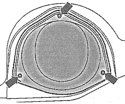
4.3. Unscrew the bolts (see arrows) fastening the cover on the bottom, which covers the fuel pump with the fuel gauge sensor
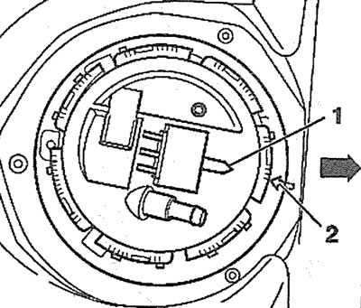
4. Disconnect plugs 1 and 2 from the fuel pump cover (see illustration).
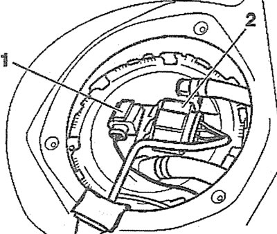
4.4. Disconnect plugs 1 and 2 from the fuel pump cover
5. Disconnect the supply 2 and return 1 fuel lines from the fuel pump cover (see illustration).
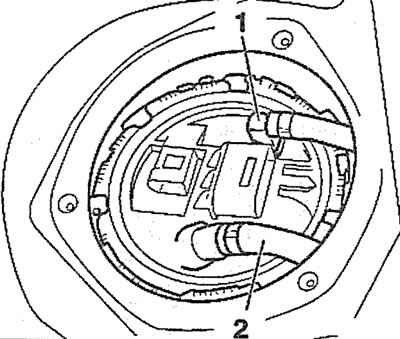
4.5. Disconnect the supply 2 and return 1 fuel lines from the fuel pump cover
6. Vehicles with parking heater. Disconnect the parking heater fuel line.
7. Unscrew the ring nut using a special key, catalog number T10202 (see illustration).
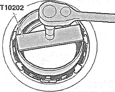
4.7. Unscrew the ring nut using a special key, catalog number T10202
8. Remove the fuel pump cover together with the sealing gasket from the hole in the fuel tank, and then disconnect the connectors 1 and 2 on the bottom of the cover (see illustration).
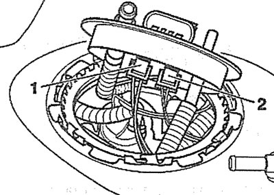
4.8. Disconnect plugs 1 and 2 on the underside of the fuel pump cover
9. Move the pump cover with the fuel lines connected to it upwards (see arrow in illustration).
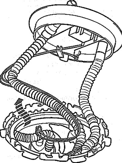
4.9. Move the pump cover with the fuel lines connected to it upwards (see arrow)
10. Reach into the fuel tank opening and disconnect the return fuel line retainer inside the tank (see arrow in illustration).
4.10. Put your hand into the fuel tank opening and disconnect the holder 1 of the return fuel line inside the tank (see arrow)
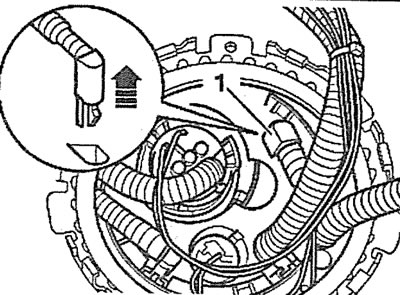
11. Insert your hand into the fuel tank opening and disconnect the fuel line guide tube 1 (see arrows in the illustration)and remove the fuel line.
4.11. Put your hand into the fuel tank opening and disconnect the fuel line guide tube 1 (see arrows)
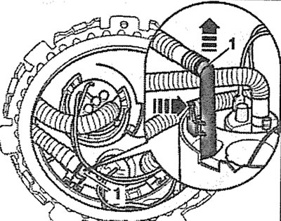
12. Press gently on the leashes (see arrows in the illustration) tee 2 and disconnect fuel line 1 from the tee.
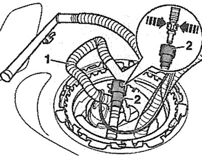
4.12. Gently press on the leashes (see arrows) tee 2 and disconnect fuel line 1 from the tee
13. Turn the fuel pump in the tank with a special key, for example, key 3307, approximately 15° to the left until it stops, thus releasing it from the bayonet clamp (see illustration).
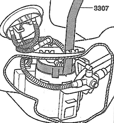
4.13. Turn the fuel pump in the tank with a special key 3307 approximately 15° to the left until it stops, thus releasing it from the bayonet clamp
14. Make sure that notch 1 on the pump body is positioned opposite mark 2, and carefully remove the fuel pump (see illustration).
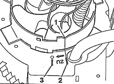
4.14. Make sure that notch 1 on the pump body is positioned opposite mark 2
15. Remove the fuel gauge sensor (see arrows in the illustration).
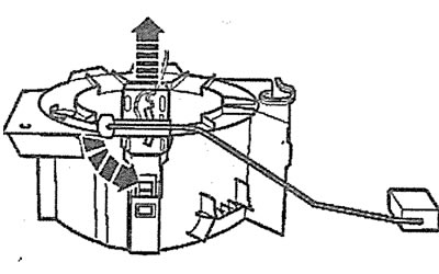
4.15. Remove the fuel gauge sensor (see arrows)
Installation
The fuel priming/fuel pump is installed in the reverse order of removal.
16. Install the fuel gauge sensor into its seat and gently press the sensor until the lock clicks into place (see arrow in illustration).

4.16. Install the fuel gauge sensor into its mounting location and gently press the sensor until the lock clicks into place (see arrow)
17. Install the fuel pump in place so that the recess 1 on the pump body coincides with the mark 3 (see illustration 4.14). Then turn the fuel pump with key 3307 all the way to the right so that notch 1 is positioned opposite mark 2 (see illustration 4.14).
18. Make sure that pointer 1 on the fuel pump cover is aligned with mark 2 on the fuel tank (see illustration).
4.18. Make sure that pointer 1 on the fuel pump cover is opposite mark 2 on the fuel tank
The original text of the material can be found on the website: audimanual.ru