
Table of contents: Removal ↓ Installation ↓
Removal
1. Remove all available fuel from the tank if it has not been used up. In workshops, a special fuel extraction device VAS 5190 is used for this purpose (see illustration 3.1).
2. Unscrew the bolts (see arrows in the illustration) fastening the cover on the bottom, which covers the jet pump with the fuel gauge sensor.
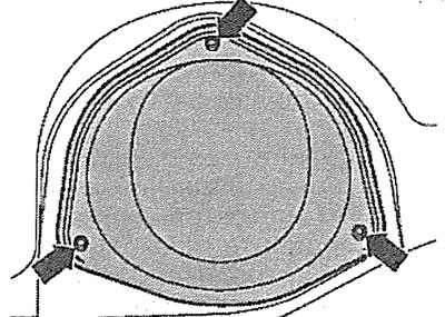
5.2. Unscrew the bolts (see arrows) fastening the cover that covers the jet pump with the fuel gauge sensor
3. Disconnect the plug (see arrow in illustration) from the jet pump cover.
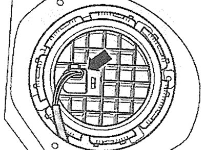
5.3. Disconnect the plug (see arrow) from the jet pump cover
4. Unscrew the ring nut using a special key, catalog number T10202 (see illustration).
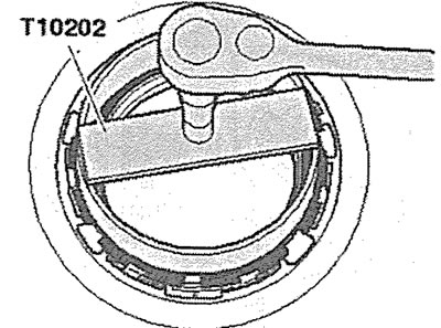
5.4. Unscrew the ring nut using a special key, catalog number T10202
5. Carefully move the fuel gauge sensor 1 from its seat in the fuel tank hole, then disconnect the sensor plug by squeezing the leashes (see arrows in the illustration) holder 2.
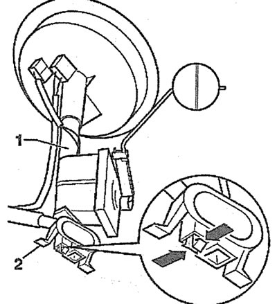
5.5. Carefully move the fuel gauge sensor 1 from its mounting location in the fuel tank opening
6. Disconnect the fuel gauge sensor and carefully remove the jet pump together with the fuel lines.
Installation
The jet pump is installed in the reverse order of removal.
The original article is posted on the resource AUDIMANUAL.RU