
Table of contents: Removal ↓ Installation ↓
Removal
Cars with gasoline engines
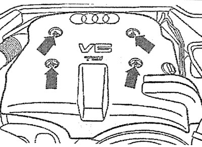
1. Remove the engine protective cover (see arrows in the illustration).
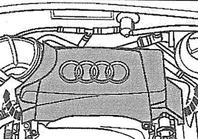
4.1 Remove the engine protective cover (see arrows)
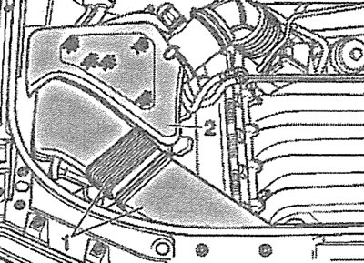
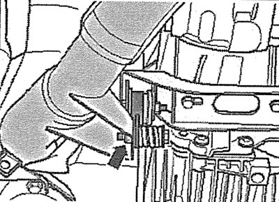
2. Disconnect the coolant hose from the expansion tank by removing clamp 1 (see illustration). Plug the hose opening with a suitable plug or clamp it.
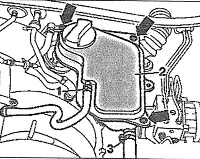
4.2. Disconnect the coolant hose from the expansion tank by removing clamp 1
3. Unscrew the bolts (see arrows in illustration 4.2) fastenings of the coolant expansion tank.
4. Disconnect the coolant level sensor plug and move the expansion tank away from the work area without disconnecting the coolant hose 3 from it (see illustration 4.2).
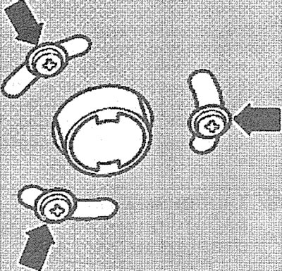
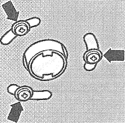
5. Unscrew the bolts (see arrows in the illustration) and disconnect the air supply hose from the afterburning system valve.
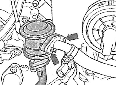
4.5. Unscrew the bolts (see arrows) and disconnect the air supply hose from the afterburning system valve
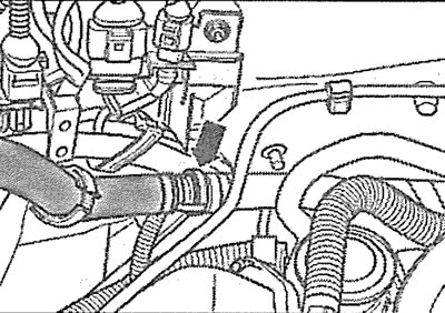
6. Loosen the clamp (see arrow in illustration) and disconnect the crankcase ventilation hose from the intake manifold.
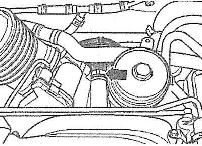
4.6. Loosen the clamp (see arrow) and disconnect the crankcase ventilation hose from the intake manifold
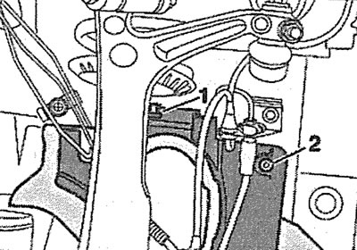
7. Remove the air filter cover 2 and disconnect the air intake 1 (see illustration).
4.7. Remove the air filter cover 2 and disconnect the air intake 1
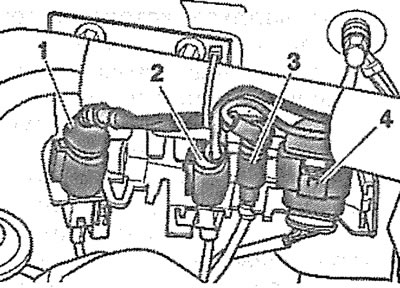
8. Disconnect plug 3 from the solenoid valve 2 for purging the adsorber and carefully remove the valve from the holder (see illustration).
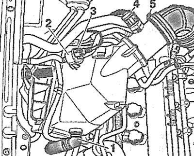
4.8. Disconnect plug 3 from the solenoid valve 2 for purging the adsorber and carefully remove the valve from the holder
9. Disconnect plug 4 of the mass air flow sensor (see illustration 4.8).
10. Carefully disconnect the hose I of the afterburning system pump (see illustration 4.8).
11. Disconnect the air duct by loosening the clamp 5 (see illustration 4.8).
12. Unscrew the bolt (see arrow in illustration 4.8) and remove the air filter housing.
13. Disconnect the air supply duct from the throttle valve by removing the corresponding mounting clamp (see arrow in illustration).
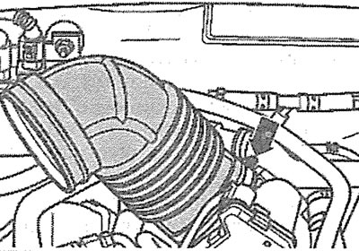
4.13. Disconnect the supply air duct from the throttle valve by removing the corresponding mounting clamp (see arrow)
14. Disconnect the air supply hose from the combined valves of the afterburning system by removing the mounting clamp (see arrow in illustration).
4.14. Disconnect the air supply hose from the combined valves of the afterburning system by removing the fastening clamp (see arrow)
15. Release from the holders and disconnect the plugs of 1-4 lambda probes (oxygen sensors), and then release the sensor wires from the fasteners (see illustration).
4.15. Release from the holders and disconnect the plugs 1-4 of the lambda probes (oxygen sensors)
16. Unscrew nuts 2 and 3 securing the intake pipe with the main and additional catalytic converters. Then remove the corresponding front wheel (see illustration).

4.16. Unscrew nuts 2 and 3 securing the intake pipe with the main and additional catalytic converters
17. Cars with parking heater. Unscrew the bolts (see arrows in the illustration) fastening the heater outlet pipe to the engine mudguard.
4.17. Unscrew the bolts (see arrows) fastening the heater outlet pipe to the engine splash guard. Cars with a parking heater
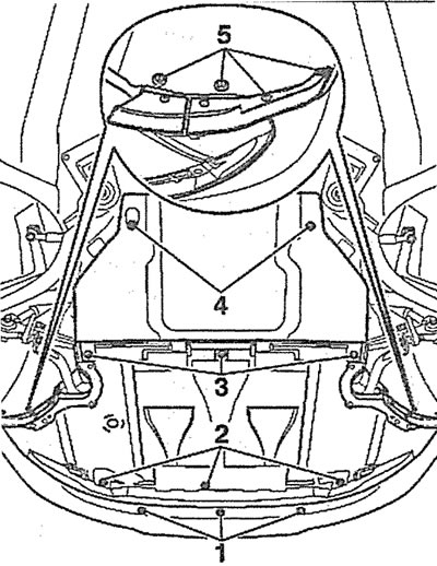
18. Unscrew the bolts/press the clamps 1-3 and remove the engine splash guard (see illustration).
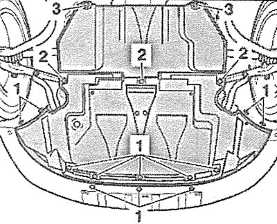
4.18. Unscrew the bolts/press the clamps 1-3 and remove the engine mudguard
19. Remove the left/right drive shaft heat shield 1 (depending on which cylinder head the intake pipe is disconnected from - right or left) (see illustration).
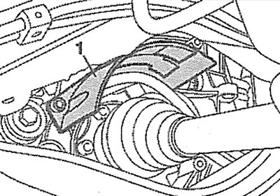
4.19. Remove the heat shield 1 of the left drive shaft
20. Remove the drive shaft.
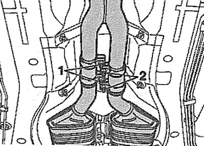
21. Unscrew the clamping bolts 1 and 2 of the intake pipe mounting clamps (see illustration).
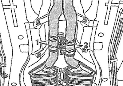
4.21. Unscrew the clamping bolts 1 and 2 of the intake pipe mounting clamps
22. Unscrew the bolts (see arrows in the illustration) and remove both heat shields.
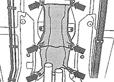
4.22. Unscrew the bolts (see arrows) and remove both heat shields
23. Unscrew the bolts (see arrows in the illustration) and remove the gearbox heat shield.
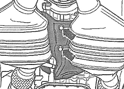
4.23. Unscrew the bolts (see arrows) and remove the gearbox heat shield
24. Remove the heat shield A of the propeller shaft (see arrows in the illustration).
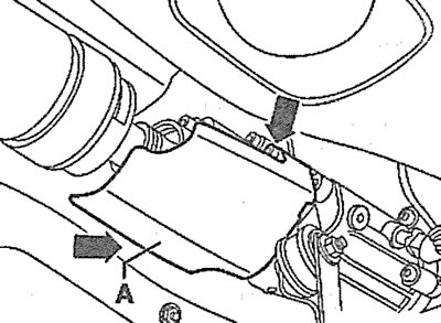
4.24. Remove the heat shield A of the propeller shaft (see arrows)
25. Disconnect the propeller shaft from the gearbox by unscrewing the bolts that secure it to the flange, lower the propeller shaft onto the exhaust pipes or tie the shaft with wire to the body.
26. Place a support or garage lift under the power unit, specifically in the area indicated by the arrow in the illustration.
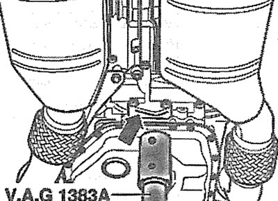
4.26. Install a support or garage lift under the power unit, namely on the area indicated by the arrow
27. Unscrew bolts 2 and 3, and then bolts 1 and 4 of the subframe mounting (see illustration).
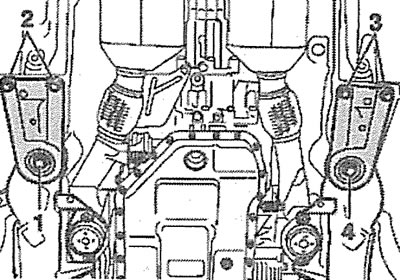
4.27. Unscrew bolts 2 and 3, and then bolts 1 and 4 of the subframe fastening
28. Carefully lower the gearbox and subframe using a garage lift.
29. Unscrew the bolt (see arrow in illustration) fastenings of the inlet pipe lining.
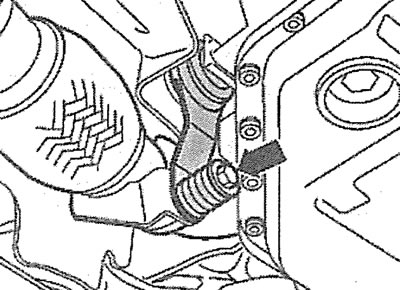
4.29. Unscrew the bolt (see arrow) fastenings of the inlet pipe lining
30. Release the lambda probe wires from the holders.
31. Unscrew nuts 1 and 3 securing the intake pipe with the main and additional catalytic converters to the exhaust manifold (see illustration) and carefully remove the pipe.
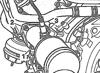
4.31. Unscrew nuts 1 and 3 securing the intake pipe with the main and additional catalytic converters to the exhaust manifold
Diesel Engine Cars
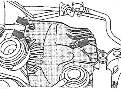
32. Unscrew the bolts (see arrows in the illustration) fasteners and remove the upper protective engine cover.
4.32. Unscrew the bolts (see arrows) fasteners and remove the upper protective engine cover
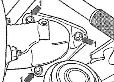
33. Cars with AFB, AKN engine. Unscrew the bolts (see arrows in the illustration) fasteners and remove the turbocharger heat shield.
4.33. Unscrew the bolts (see arrows) fasteners and remove the turbocharger heat shield. Cars with AFB, AKN engines
34. Unscrew bolts 1 (see illustrations 4.34 and 4.34a) fasteners and disconnect the inlet pipe with the additional catalytic converter from the turbocharger.
4.34. Unscrew the bolts 1 of the fastening and disconnect the inlet pipe from the turbocharger. Cars with AFB.AKN engine |
4.34a. Unscrew the bolts 1 of the fastening and disconnect the inlet pipe from the turbocharger. Cars with AKE, AYM, BAU, BCZ, BDG, BDH, BFC engines |
35. Remove the front left wheel.
36. Cars with parking heater. Unscrew the bolts (see arrows in the illustration) fastening the heater outlet pipe to the engine mudguard.
4.36. Unscrew the bolts (see arrows) fastening the heater outlet pipe to the engine splash guard. Cars with a parking heater
37. Unscrew bolts/press fasteners 1-3 and remove engine splash guard (see illustration).
4.37. Unscrew the bolts/press the clamps 1-3 and remove the engine mudguard
38. Unscrew bolt 2, press lock 1 and remove the protective shield of the left drive shaft (see illustration).
4.38. Unscrew bolt 2, press lock 1 and remove the protective shield of the left drive shaft
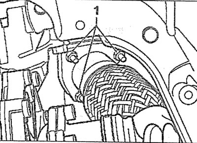
39. Remove the heat shield 1 of the left drive shaft (see illustration).
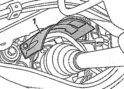
4.39. Remove the heat shield 1 of the left drive shaft
40. Unscrew the nut(see arrow in illustration) fastenings of the inlet pipe lining.
4.40. Unscrew the nut (see arrow) fastenings of the inlet pipe lining
41. Unscrew the clamping bolts 1 and 2 of the intake pipe mounting clamps and carefully remove the intake pipe (see illustration).
4.41. Unscrew the clamping bolts 1 and 2 of the intake pipe mounting clamps
Installation
The installation of the exhaust pipe is carried out in the reverse order of removal.
(This publication is borrowed from the resource AUDImanual.ru)