
Table of contents: Removal ↓ Installation ↓
Removal
Cars with gasoline engines
1. Remove the engine (see the relevant chapter).
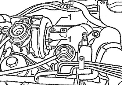
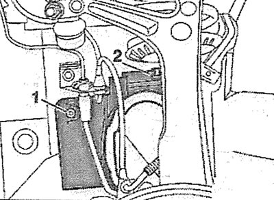
2. Disconnect plugs 1 and 4 (left cylinder head) or plugs 1 and 2 (right cylinder head) lambda probes (see illustrations 6.2 and 6.2a) and release the wires from the fasteners.
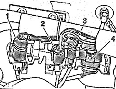
6.2. Disconnect plugs 1 and 4 of the lambda probes. Left cylinder head |
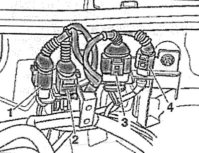
6.2a. Disconnect plugs 1 and 2 of the lambda probes. Right cylinder head |
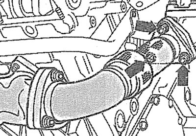
3. Disconnect the intake pipe from the exhaust manifold by unscrewing nuts 1-3 of its fastenings (see illustrations 6.3 and 6.3a).
6.3. Disconnect the intake pipe from the exhaust manifold by unscrewing nuts 1-3 of its fastening. Left cylinder head |
6.3a. Disconnect the intake pipe from the exhaust manifold by unscrewing nuts 1-3 of its fastening. Right cylinder head |
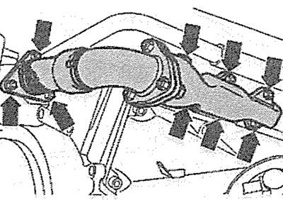
4. Disconnect the coolant pipe from the corresponding cylinder head by unscrewing the bolts and removing the mounting clamps (see illustration).
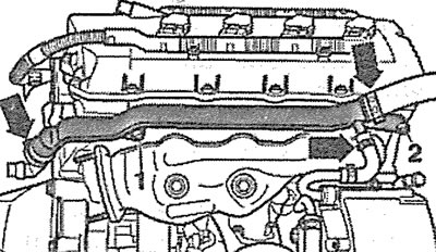
b.4. Disconnect the coolant pipe from the right cylinder head by unscrewing bolts 1 and 2 and removing the mounting clamps (see arrows)
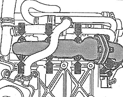
5. Unscrew nuts 1-12 and carefully remove the exhaust manifold (see illustrations 6.5 and 6.5a). The tightening torque of the nuts is 25 Nm.
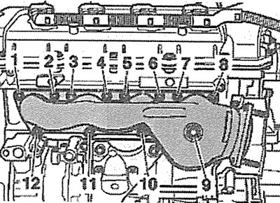
6.5. Unscrew nuts 1-12 of the fastening and carefully remove the exhaust manifold. Left cylinder head |
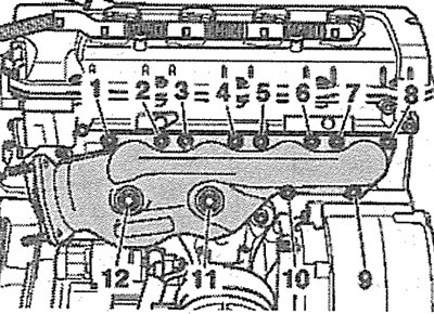
6.5a. Unscrew nuts 1-12 and carefully remove the exhaust manifold. Right cylinder head |
Diesel Engine Vehicles Left Cylinder Head
6. Remove the intake pipe with the main catalytic converter (see the relevant chapter).
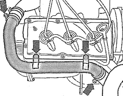
7. Unscrew the bolts (see arrows in the illustration) and remove the turbocharger heat shield.
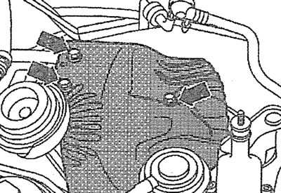
6.7. Unscrew the bolts (see arrows) and remove the turbocharger heat shield
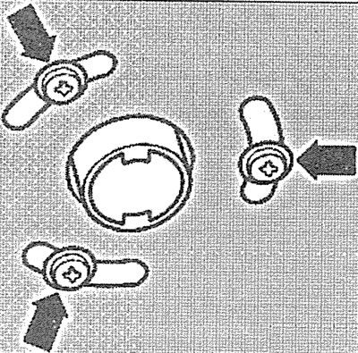
8. Unscrew the nuts 1 fasteners remove the additional catalyst (see illustration). The tightening torque of the nuts is 25 Nm.
6.8. Unscrew the nuts 1 of the fastening and remove the additional catalyst
9. Unscrew the bolts (see arrows in the illustration) and disconnect the connecting pipe from the flange.
6.9. Unscrew the bolts (see arrows) and disconnect the connecting pipe from the flange
10. Unscrew the mounting nuts (see arrows in the illustration) and carefully remove the exhaust manifold together with the connecting pipe.
6.10. Unscrew the fastening nuts (see arrows) and carefully remove the exhaust manifold together with the connecting pipe
Right cylinder head
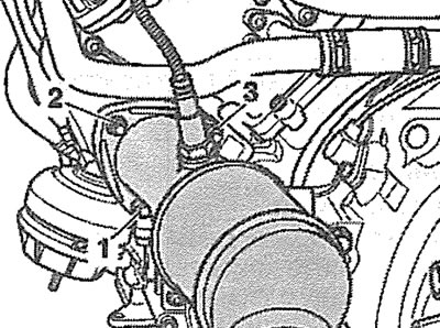
11. Remove the air filter cover 2 and disconnect the air intake 1 (see illustration).
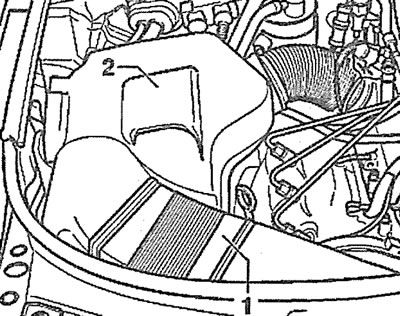
6.11. Remove cover 2 of the air filter and disconnect the air intake 1
12. Unscrew the bolts (see arrows in the illustration) fasteners and remove the upper protective engine cover.
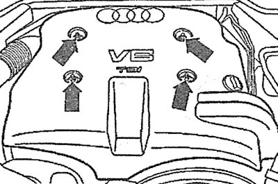
6.12. Unscrew the bolts (see arrows) fasteners and remove the upper protective engine cover
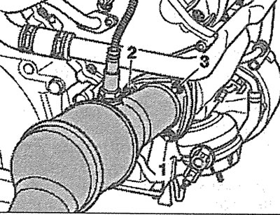
13. Remove clamp 3, disconnect plug 4, then hose 2, unscrew bolt 1 and remove the air filter housing (see illustration).
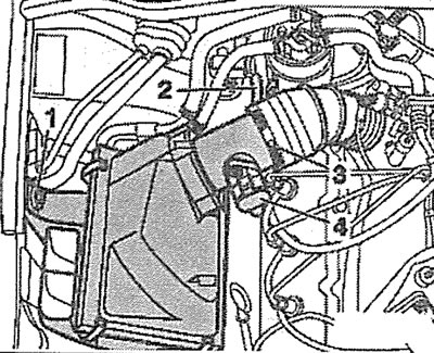
6.13. Remove clamp 3, disconnect plug 4, then hose 2, unscrew bolt 1 and remove the air filter housing
14. Unscrew the bolts (see arrows in the illustration) holders and remove the air supply hose from the turbocharger to the intercooler.
6.14. Unscrew the bolts (see arrows) holders and remove the air supply hose from the turbocharger to the intercooler
15. Remove the front right wheel.
16. Cars with parking heater. Unscrew the bolts (see arrows in the illustration) fastening the heater outlet pipe to the engine mudguard.
6.16. Unscrew the bolts (see arrows) fastening the heater outlet pipe to the engine splash guard. Cars with a parking heater
17. Unscrew bolts/press fasteners 1-5 and remove engine splash guard (see illustration).
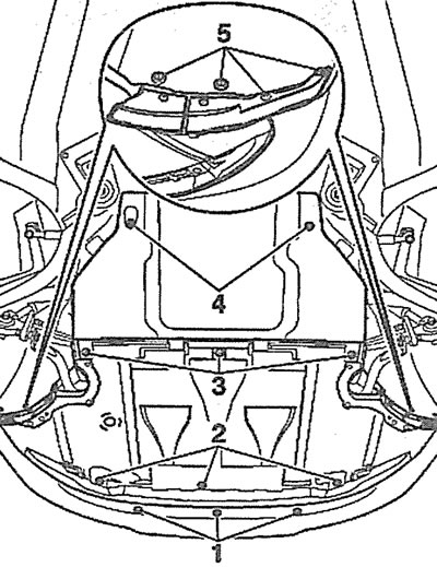
6.17. Unscrew the bolts/press the clamps 1-5 and remove the engine splash guard
18. Unscrew bolt 1, press lock 2 and remove the protective shield of the right drive shaft (see illustration).
6.18. Unscrew bolt 1, press lock 2 and remove the protective shield of the right drive shaft
19. Unscrew the nuts (see arrows in the illustration) and remove the exhaust manifold together with the connecting pipe.
6.19. Unscrew the nuts (see arrows) and remove the exhaust manifold together with the connecting pipe
Installation
The exhaust manifold is installed in the reverse order of removal.