



Table of contents: Fit ↓ Fitting the door's supporting part ↓
A special feature of AUDI cars is their two-piece doors. The inner part, where the door elements are attached, is connected to the outer part of the door with four bolts. In the event of an accident with damage to the door, its outer part can be replaced without wasting time on the laborious process of attaching and adjusting the window lifter and lock mechanism.
Door seals require special care because cracks in the seals not only lead to the door being sealed, but also to increased noise from the flow around the vehicle while driving.
When installing the door bearing part, it should be secured according to the marks made before removal, screw in the fastening bolts 3, 4, 6, 9 and the adjusting wedges 2 and 7 and tighten them slightly. Install the assembled door, close it and check its position. If necessary, adjust it, and then tighten the bolts in the sequence 3, 9, 6 and 4 with a force of 30 Nm.
If the wedge is not enough to perform the necessary adjustment, then a spacer washer of the appropriate thickness can be placed underneath it.
Attention! It is not allowed to install two adjusting wedges in one place at the same time.
The door is installed in the reverse order of removal.
Fit
Caution: Before fitting the front door, the rear door must be fitted first or it must already be installed properly.
1. Unscrew the mounting bolts and remove the door lock bracket.
2. Fit the door in a longitudinal position. To do this, loosen the hinge bolts on the front pillar so that the door and hinges can be moved in the longitudinal direction.
3. Fit the door so that the nominal gaps are observed and tighten the hinge mounting bolts with a force of 30 Nm.
Nominal door gap values:
- A - 3.0 mm + 1 mm;
- B - 4.5 mm±0.5 mm;
- C - 3.5 mm ±0.1 mm.
4. Fit the door transversely. To do this, loosen the bolts securing the hinges to the door so that the door can be moved in the longitudinal holes of the hinges. Move the door and fit it so that it is flush with the adjacent body parts. This primarily applies to the front part of the door. The rear part of the door is fitted by moving the lock bracket.
5. Tighten the door hinge mounting bolts to 30 Nm.
6. Open the door and loosen the bolts securing the lock bracket so that the bracket can be moved by applying a certain amount of force. Install the lock bracket so that the door protrudes slightly outward.
7. Carefully close the door and move it together with the bracket inward so that the door is positioned exactly along the contour of the body.
8. Carefully open the door and tighten the bracket bolts to 20 Nm.
Attention! The position of the lock bracket can only be changed horizontally. The height of the bracket is not adjustable.
Fitting the door's supporting part
Before fitting the top of the door, the door itself as a whole must already be fitted.
9. Loosen the bolts securing the door's supporting top so that the top or adjusting wedges can be moved. An assistant is required to perform the adjustment, and must be in the passenger compartment.
10. Close the door. The assistant should push the door from the inside towards the A-pillar and the ceiling.
11. Check the position of the door bearing part in the door opening from the outside. The door seal projection should fit against the front pillar and the roof frame according to the contour.
12. Ask an assistant in the car to push the door towards him/herself. The force applied should be slightly excessive so that the rubber seal on the door is compressed.
13. Move the adjusting wedge 7 properly to fit the door relative to the center pillar (see illustration 10.0).
14. Carefully open the door and tighten bolts 3, 9, 6, 4 in the sequence shown (see illustration 10.0).
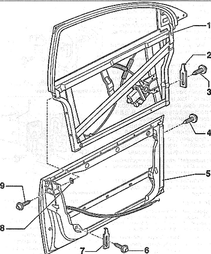
10.0. Front door assembly:
1 - the top of the door with the bracket of the hinged mechanisms. To dismantle it, it is necessary to remove the door trim, disconnect the power plugs and remove the wires. After that, mark the position of the top of the door with a thin felt-tip pen, unscrew bolts 3, 9, 6 and 4 and remove the supporting part of the door
2, 7 - adjusting wedge. Installation of the wedge is mandatory. By shifting the wedge 7, it is possible to tilt the top of the door relative to the middle pillar of the body
3 - bolt. Tightening torque 30 Nm
4 - bolt. Tightening torque 30 Nm
5 - the lower part of the front door. When removing it, it is not necessary to disconnect the supporting part of the door. Remove the lower part of the door trim, disconnect the plugs located on the door pillar, as well as the corrugated cover of the wiring harness. After that, disconnect all the wires from the front pillar. Unscrew the bolts securing the upper and lower door hinges with a T45 socket wrench and remove the door (see..illustrations 10.0a and 10.06)
6 - bolt. Tightening torque 30 Nm
8 - self-adhesive gasket 9± bolt. Tightening torque 30 Nm
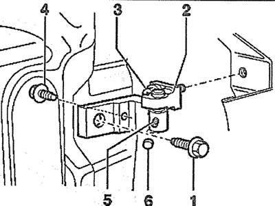
10.0a. Upper door hinge:
1 - Hexagon head bolt. Tightening torque 30 Nm
2 - top loop
3 - bolt with a head with an internal hexagon for a T45 socket wrench
4 - bolt. Tightening torque 30 Nm. Screwed in from the interior side
5 - threaded pin. Tightening torque 23 Nm
6 - plug for the hole for the threaded pin
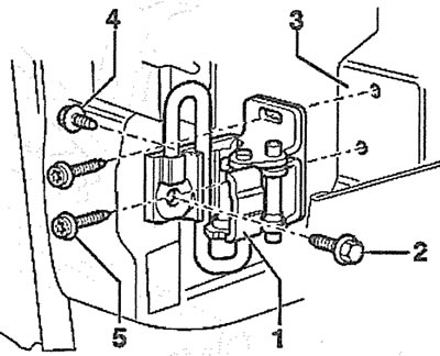
10.06. Lower door hinge:
1 - bottom loop
2 - bolt. Tightening torque 30 Nm
3 - front door
4 - bolt. Tightening torque 30 Nm
5 - bolt with a socket head with an internal hexagon. Tightening torque 30 Nm
This article was copied from the website AUDIMANUAL.ru