
Table of contents: Removal ↓ Installation ↓
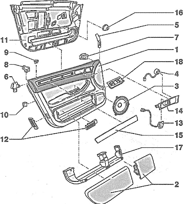
11.0. Door trim:
1 - upholstery
2 - pockets
3 - speaker
4 - high-tone speaker
5 - internal adapter
6 - external adapter
7 - internal insert
8 - external insert
9 - power button guide
10 - linings
11 - profiled seal
12 - door light
13 - Central lock switch
14 - inner door handle drive
15 - overlay
16 - foam insert
17 - fastening pockets
18 - window lift switch block
Removal
1. Insert a thin screwdriver 1, holding it at an angle, into the hole 2 on the door handle (see illustration).
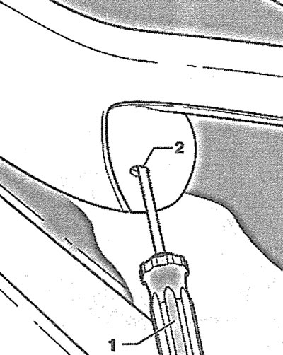
11.1. Insert a thin screwdriver 1, holding it at an angle, into the hole 2 on the door handle
Attention! For front doors (driver's and passenger's) the screwdriver should be inserted into the hole, holding it vertically and pressing the screwdriver handle against the door trim.
2. Press the screwdriver 3 upwards until a noticeable resistance appears. In this case, the screwdriver is located between the door armrest and the retaining lug 2 of the switch (see illustration).
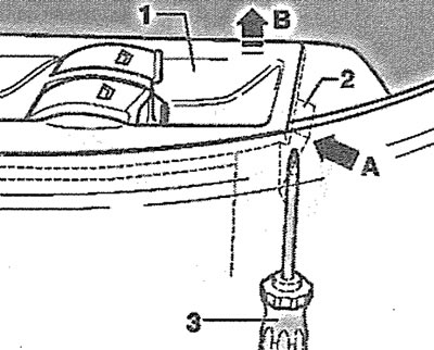
11.2. Press screwdriver 3 upwards until you feel a noticeable resistance
3. Press the projection 2 of the switch with a screwdriver, acting as shown by arrow A in Illustration 11.2. In this position, press the screwdriver further upwards (see arrow B in Illustration 11.2), to push the switch out of the armrest.
4. Press out the protrusion 2 with a narrow screwdriver and disconnect the plug 1 from the switch (see illustration).
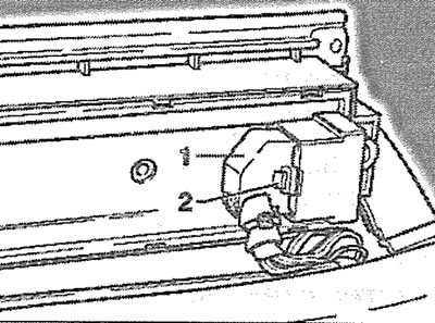
11.4. Press out the protrusion 2 with a narrow screwdriver and disconnect the plug 1 from the switch
5. Unscrew the two bolts 2 from the door trim 1 (see illustration 11.0a).
6. Slide the door trim up approximately 20 cm and remove it from the door.
7. Release the lock drive rod 1 from the holder on the guide 2 and disconnect its hook 3 from the inner handle (see illustration).
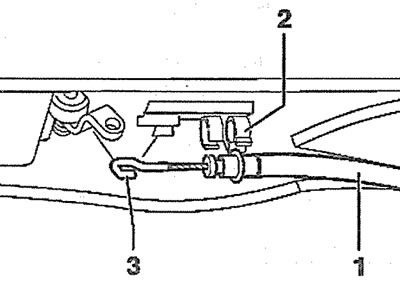
11.7. Release the lock drive rod 1 from the holder on the guide 2 and disconnect its hook 3 from the inner handle
Attention! When installing, the hook must face upwards.
8. Remove the connectors from the holders and disconnect them from the rear side of the door trim (see illustration).
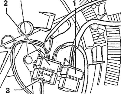
11.8. Remove from the holders and disconnect the plugs on the back of the door trim:
1 - central lock switch plug
2 - door light and security alarm plug
3 - speaker plug
Installation
9. Make sure that the rubber pads 3 and 4 of the clamps are in place (see illustration 11.0a).
10. Make sure that the profiled seal fits tightly around the entire perimeter. If necessary, tuck the seal into the guide grooves.
11. Replace the door trim, connect the plugs and secure them in the holders.
12. Pass the power wire of the window lift motor through the hole in the trim and plug the hole with a suitable insert.
13. Secure the inner handle drive cable so that the fastening hook faces upwards (see illustration 11.7).
14. Insert the drive cable housing into the guide.
15. Press the guide sleeve of the lock release button out of the upholstery.
Attention! If the guide cannot be pressed out, then tape a thin wire to the top of the button and insert it into the hole in the trim. When installing the door trim, pull the lock release button into the guide bushing using the wire.
16. Secure the door trim above the door openings, working together with an assistant.
17. Press the upholstery against the door, move it down and fix it. In this case, the upholstery should be pressed firmly near the fasteners 4 (see illustration 11.0a).
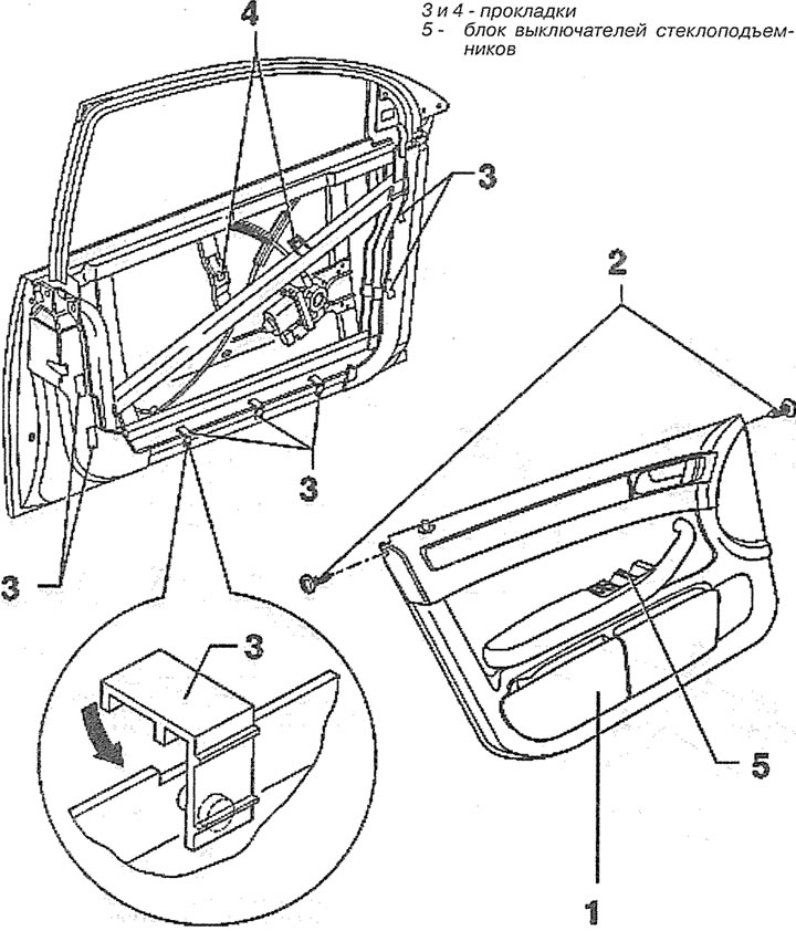
11.0a. Unscrew the two bolts 2 from the door trim 1
18. Connect the window switch plug and secure it.
19. Insert the rear part of the window switch into the hole on the armrest, and then press its front part and fix it in the mounting place.
20. Screw in the two door trim mounting bolts and tighten them to 1.5 Nm.