
Table of contents: Removal ↓ Installation ↓
Vacuum pipeline connections (6-cylinder engine with 174 hp)
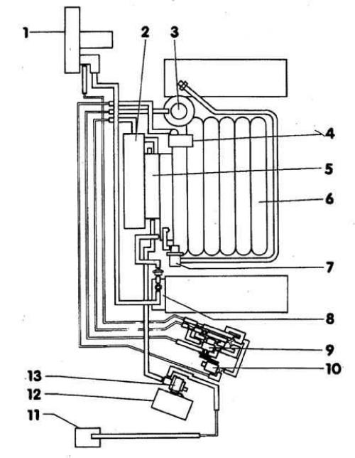
- 1. Brake booster
- 2. Noise damper
- 3. Mechanical valve of the exhaust gas recirculation system
- 4. Diaphragm mechanism of the intake manifold bypass valves
- 5. Throttle valve assembly
- 6. Switchable intake manifold
- 7. Fuel pressure regulator
- 8. Vacuum pump
- 9. Exhaust gas recirculation solenoid valve
- 10. Intake manifold valve switching control valve
- 11. Intake manifold capacity
- 12. Air filter
- 13. Solenoid valve 1 of the activated carbon system
Removal
1. Disconnect the oxygen sensor connector. The connector is secured to the front wall of the cabin. The 6-cylinder engine has 2 oxygen sensors. Accordingly, there are 4 connectors: 2 for heating the sensors and 2 for signals. The connectors for heating the oxygen sensors are black and are located on the left and right of the front wall connector panel. The connectors for the sensor signals are located slightly below the connector panel, next to the black connectors.
2. Loosen all the clamps and mark the position of the clamps with a felt-tip pen.
3. Remove the oxygen sensor from the exhaust pipe.
Installation
1. Lubricate the oxygen sensor threads with G5 mounting paste.
Warning: The grease must not reach the edges of the oxygen sensor housing.
2. Insert the oxygen sensor and tighten to 50 Nm.
3. Connect the plug connectors of the heating and signal circuits.
4. Secure the electrical wires with clamps. Make sure that the clamps are installed in the same place where they were before removal. This is necessary to avoid the wires touching the exhaust system.
The original publication in its entirety is posted on the website: AUDIMANUAL.ru