



To remove the device, remove the trim in front of the glove compartment, press the collet against the cross wall and pull the control device down.
Chapter "Adjusting the gas drive" and "Intake manifold heating" as well as for Keihin carburetors.
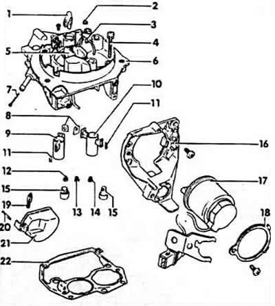
Upper part of the carburetor
1 - ventilation pipe (float chamber)
2 - protective net (float chamber ventilation)
3 - enrichment tube at full load
4 - mounting bolt, 5 Nm
5 - pre-throttle (air damper)
6 - upper part of the carburetor
7 - grid
8 - gaskets (always replace)
9 - atomizer, chamber I
10 - atomizer, chamber II
11 - locking wedge
12 - idle fuel jet
13 - main jet, chamber I
14 - main jet, chamber II
15 - cork
16 - holder
17 - Pre-throttle regulator
18 - fastening ring
19 - float needle
20 - float axis
21 - float
22 - gasket
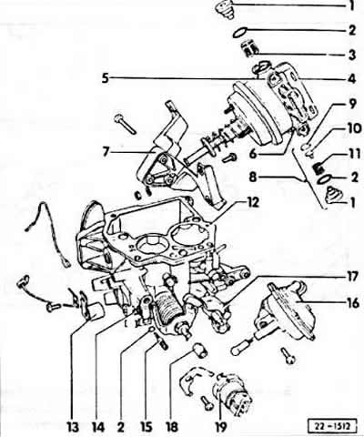
Lower part of the carburetor
1 - cork
2 - circular section seal
3 - filter
4 - throttle valve regulator
5 - ventilation valve
6 - air bleed valve
7 - throttle valve and gas drive regulator holder
8 - check valve
9 - valve plate
10 - guide
11 - valve spring
12 - lower part of the carburetor
13 - Medium load channel heater
14 - throttle stop screw, chamber I
15 - CO adjustment screw
16 - vacuum ignition regulator, chamber II
17 - throttle lock lever, chamber II
18 - connecting sleeve
19 - throttle potentiometer