
Removal
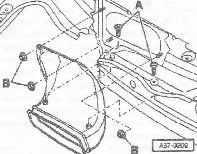
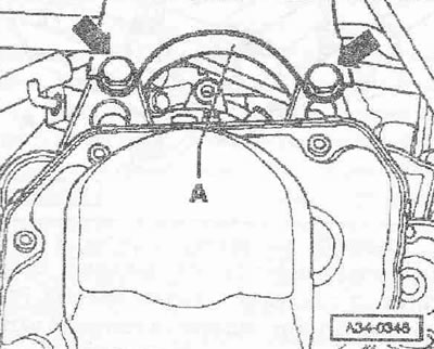
Disconnect the battery ground wire with the ignition off. Remove the rubber seal on the water drainage box. Remove the windshield wiper arm and fairing. Remove both bolts "A" and three hex nuts "B". Remove the fresh air intake duct forward.
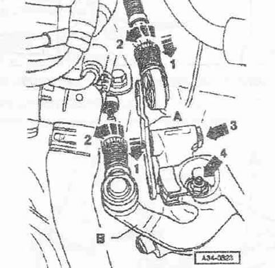
Pull the safety mechanism on the switching cable and on the selection cable forward until it stops "arrow 1" and then lock it by moving left "arrow 2". Remove the locking washer "arrow 3" from the intermediate lever "A" and remove the intermediate lever. Remove the gearbox selector "B", then unscrew the nut "arrow 4".
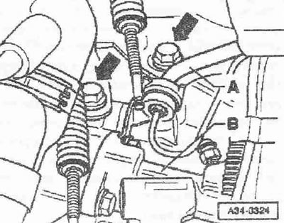
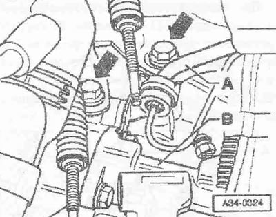
Remove the pipe-hose line "A" from the gearbox bracket. Remove the clutch slave cylinder "B" and put it aside, secure it with wire, do not open the lines.
Instructions: Do not press the clutch pedal.
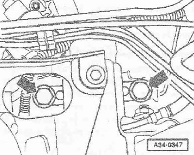
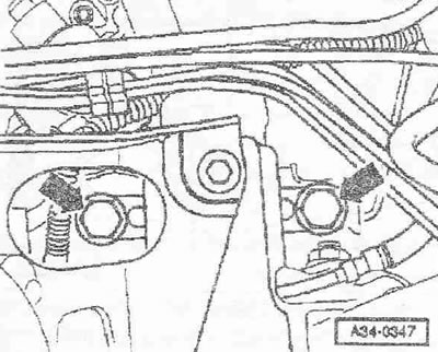
Unscrew 2 bolts of the cable counter support from the gearbox "arrows". The third bolt of the cable counter support on the gearbox is removed from below on a raised car. Remove the ground wire from the upper connecting screw of the gearbox to the engine. Then unscrew the upper mounting bolt on the starter.
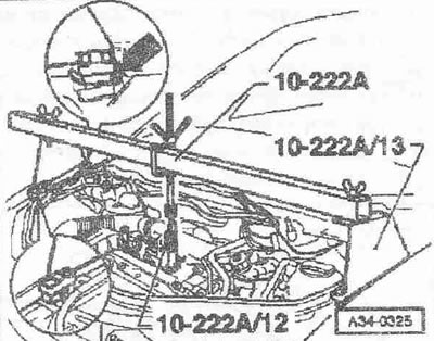
Install the crossmember "10.222 A" together with the adapter "10.222 A/13" and the hook "10.222 A/12". Connect the adapter "10.222 A/13" at the rear to the hood fastening hook "arrow". Slightly tighten the engine with the gearbox using the lead screws. Loosen the wheel bolts of the left front wheel. Raise the car. Remove the left wheel. Remove the sound insulation.
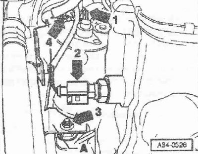
Remove the connector arrow "1" of the starter. Disconnect the connector of the reverse light switch "F4" arrow "2". Remove the bracket "A" from the starter arrow "3". Unscrew the wire arrow "4" to the traction relay, terminal 30. Remove the starter.
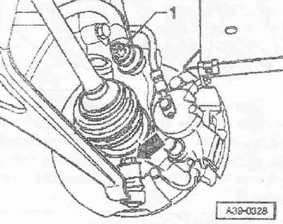
Remove screen "1" from pendulum support "2". Remove pendulum support "arrows A and B". Disconnect drive shafts from shafts with gearbox flange. Lift up right drive shaft and secure.
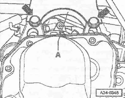
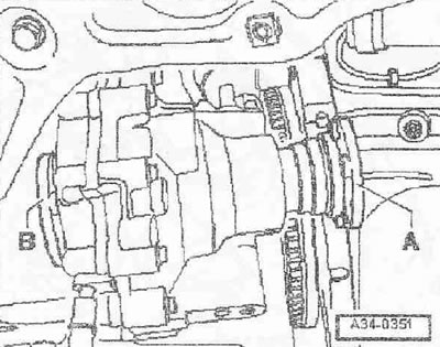
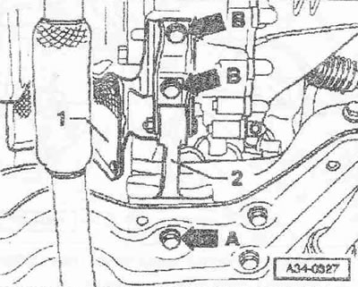
If available, disconnect the "G22" "arrow" speedometer sensor connector. Unscrew the third bolt "A" from the cable counter support on the gearbox. Then secure the shift cable and gear selection cable at the top. Unscrew the engine/gearbox connecting bolt "A" above the shaft with the flange on the right.
Disconnect the left stabilizer strut "1". Disconnect the left arm from the steering knuckle "arrow". Remove the mudguard on the left wheel arch. Turn the steering knuckle outward. Remove the left drive shaft through the opening between the subframe and the gearbox. At the same time, insert the drive shaft into the wheel arch and secure it, for example, with wire on the shock absorber strut.
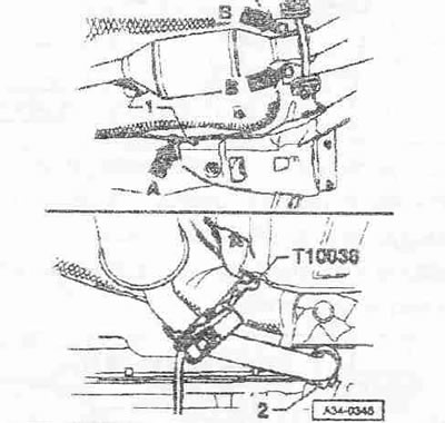
Disconnect wire "1" of the lambda probe from the heat shield "arrow A". Unscrew the exhaust system bracket from the bottom of the car "arrow B". Disconnect the exhaust system at the double clamp "2". Secure the exhaust system to the heat shield using harness T10038-.
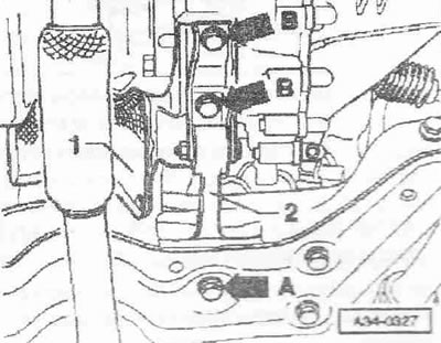
Remove the hexagonal head bolts of the "arrow" of the left support of the power unit from the gearbox port. Give the power unit an inclined position, for this purpose lower the crossmember "10.222 A" using the lead screws. When lowering the power unit, ensure that the gearbox does not touch the support of the power unit in the area of the subframe. The bolts of the "arrow" of the gearbox console "A" must be accessible.
Remove the console of the gearbox "A" "arrows". Assemble the tilter with the bracket of the gearbox "3282", the installation template "3282/31" for the gearbox "02T" and fasteners as follows: install the adjustment template "3282/31" on the bracket of the gearbox "3282". (The alignment template has only one mounting position). Position the gearbox bracket clamps in accordance with the holes in the adjustment template.
Screw the fasteners "A" onto the adjustment template as shown in Fig.
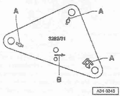
Place the tilting device under the vehicle, the arrow symbol "B" on the installation template indicates the direction of vehicle movement. Align the adjustment template parallel to the gearbox and secure the locking support to it. Unscrew the lower connecting screws of the gearbox to the engine. Unscrew the connecting screws of the engine/gearbox connection "arrow". Press the gearbox away from the fitted bushings and carefully tilt it toward the subframe. Carefully move the engine forward with the help of a second mechanic. Turn the gearbox down in the differential area.
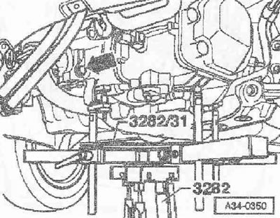
After this, carefully lower the gearbox, while moving it with the right shaft with flange "A", as shown, in the flywheel area and the left shaft with flange "B" in the subframe area. Change the position of the gearbox when lowering with the lead screws of the mounting bracket "3282".
Installation
The gearbox is installed in the reverse order. In this case, install the power unit cushion without tension.
Instructions. Clean the splines of the input shaft and apply a thin layer of plastic grease for clutch disc splines "G 000 100" to them. When replacing the gearbox, pay attention to the correct installation of the metal spacer. Check the presence of fitted bushings in the cylinder block for centering the engine/gearbox, if necessary, insert bushings. Check the transmission oil. Install the starter/wire. Attach the strut to the stabilizer and the lever to the steering knuckle. Adjust the gear shift mechanism. After connecting the battery, check and activate all vehicle systems (radio, clock, electrics of the Comfort system).
Tightening torques
Gearbox to engine
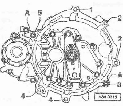
| Pos. | Bolt | Pcs. | Nm |
| 1 1) | M 12x65 | 1 | 80 |
| 2 2) | M12X140 | 2 | 80 |
| 3 | M 12x80 | 1 | 80 |
| 4 | M 10x50 | 2 | 45 |
| 5 | M 12x65 | 1 | 80 |
| A | Centering bushings | ||
1) Bolt with threaded pin M8
2) Additionally, a starter to the gearbox
Gearbox console "A" to the gearbox
Replace the bolts. Bolts "arrows" 50 Nm and tighten by 90°.
KP to the body
Replace the bolts. Bolts "arrows" 40 Nm and tighten by 90°.
Lower support of the power unit
Replace bolts. Bolt "A": 40 Nm and tighten by 90°. Bolts "B": 50 Nm.
- Cable stops to gearbox: 20 Nm
- Gear shift lever to gearbox: 20 Nm 1)
- Slave cylinder to gearbox: 23 Nm
- Double clamp to exhaust pipe: 40 Nm
- Screen to pendulum support: 23 Nm
1) Replace the nut.
Information obtained from this resource AUDIMANUAL.ru