
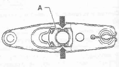
Removal
Press the locking tabs "arrow" on the back of the clutch release lever and remove the release bearing "A" from it. To install, press the release bearing "A" into the clutch release lever so that the fastening tabs "arrow" are fixed.
Clutch repair
Instructions. Before replacing the clutch disc and pressure plate, check whether there are centering bushings for centering the engine/gearbox in the cylinder block, and insert them if necessary. If there are no centering bushings, there will be difficulties when shifting, clutch problems and, accordingly, noise in the gearbox (crackling noise in drive wheels). Replace the clutch disc/pressure plate with damaged or loose rivets. Select the clutch disc and pressure plate using the electronic parts catalog and the engine letter designation.
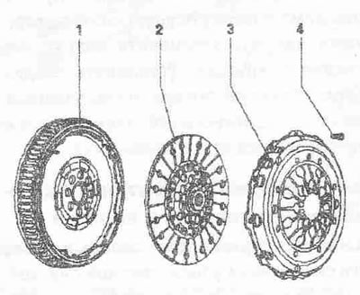
1. Flywheel. Make sure that the centering pins are securely installed; there should be no grooves, oil stains or traces of grease on the working surface of the clutch linings.
2. Clutch disc. Select the pressure plate according to the electronic parts catalog and the engine letter designation. Installation position with a dual-mass flywheel: the shorter end of the hub "arrow" faces the pressure plate. Installation position with a conventional flywheel: the clutch housing faces the pressure plate. Center. Lightly lubricate the splined connection with consistent grease. Clean the splines of the input shaft, and if using a used clutch disc, also the splines of its hub, remove traces of corrosion and apply a very thin layer of plastic grease for clutch disc splines "G 000 100" to the splines. Then move the clutch disc back and forth until the hub moves easily on the shaft. Be sure to remove excess grease.
3. Plate. Installation is possible only in one position. Check the ends of the membrane spring, check the key and riveted connections. The plates are protected against corrosion and lubricated with consistent grease. Only cleaning their working surface is allowed, otherwise the service life of the clutch will be significantly reduced.
4. Screw. Select from the electronic parts catalog. M6 = 13 Nm, M7 = 20 Nm, loosen and tighten in stages crosswise.
Mounting position of the pressure plate
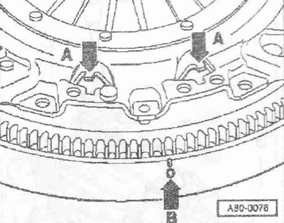
The TDC marking "B" on the flywheel must be located between the two reference marks "A".
Checking the ends of the membrane spring
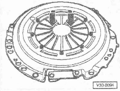
Wear of up to half the thickness of the diaphragm spring petals is acceptable.
Check keyed and riveted joints
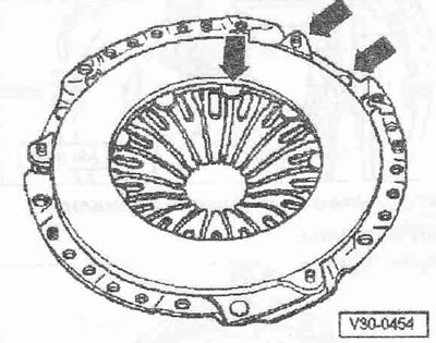
Check the spring connections between the pressure plate and the cover for cracks, and the riveted connections for secure installation. A pressure plate with damaged spring connections or with weak riveted "arrow" connections must be replaced.
Removal and installation the friction clutch
Remove the CP.
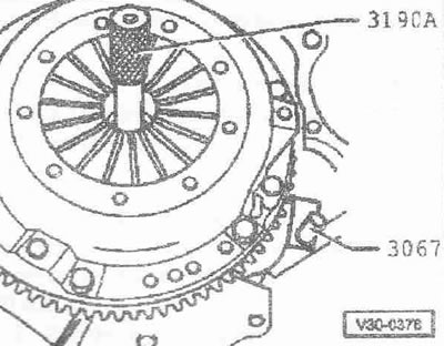
Insert support "3067" for loosening and tightening bolts. Loosen screws little by little, crosswise. Remove pressure plate and clutch disc.
Installation
Place the pressure plate on the centering pins. Tighten all screws evenly by hand until the screw head is flush with the pressure plate. Tighten the bolts gradually in a cross pattern to avoid damaging the centering holes of the pressure plate and the centering pins of the flywheel. Install the gearbox.