
Table of contents: Installation diagram of the… ↓ Removal the pyropatron of the… ↓ Installation ↓ Driver's airbag ↓ Removal Airbag with pyropatron "N95"… ↓ Installation ↓
Installation diagram of the pyropatron for disconnecting the battery
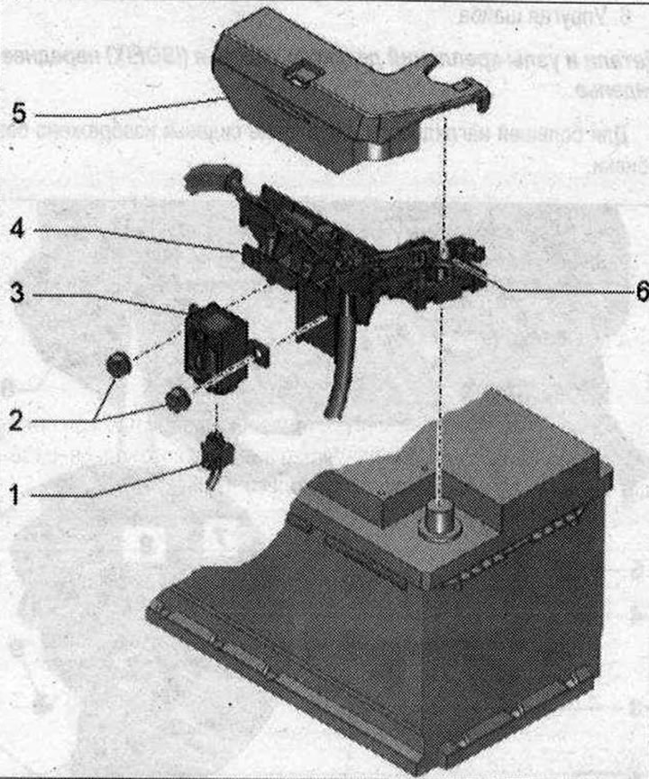 1. Electrical connector of the pyropatron for disconnecting the battery "N₂53"; 2. Nut. 15 Nm; 3. Battery disconnection pyropatron "N₂53" is supplied only together with "pos. 4"; 4. Fuse block A "SA" is supplied only together with "pos. 3"; 5. Fuse holder cover A "SA"; 6. Positive terminal
Removal the pyropatron of the battery terminal "N₂53"
Note. If the airbag indicator lamp "K75" lights up after an accident, check with whether the collision data has been saved. If the data has been saved, check whether the fault memory for item Battery isolation igniter "N₂53" has been entered as "001 Resistance too high". If this entry has been entered, replace battery isolation igniter "N₂53". Battery isolation igniter "N₂53" opens the electrical circuit every time the airbag is triggered. Battery isolation igniter "N₂53" must be replaced after it has been triggered. Battery isolation igniter "N₂53" is supplied as a spare part together with fuse bracket A "SA". To replace the battery isolation igniter "N₂53" separately, it can be unscrewed as a spare part and installed on the front fuse bracket A "SA" as described below.
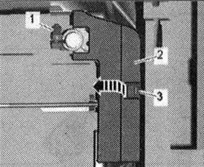
Turn on the ignition. Disconnect the battery ground cable with the ignition on. Loosen the nut "1" a few turns and remove the battery terminal of the positive wire with the fuse block A "SA" from the battery pole. Remove the fuse block A "SA" upwards. Unlock the locking spring "3" and fold back the cover "2" over the fuse block A "SA" upwards "arrow".
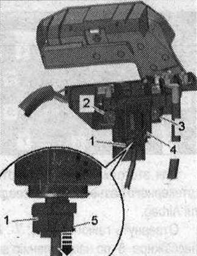
Unscrew nuts "2" and "3". Remove the pyropatron of the battery disconnect device "4". Remove the retainer "5" downwards "arrow" and disconnect the electrical connector.
Installation
Installation in reverse order, taking into account that the electrical connectors must be inserted until they stop with an audible lock. Connect the battery ground cable with the ignition on. Then query the Airbag control unit malfunction message memory and process them if necessary.
Driver's airbag
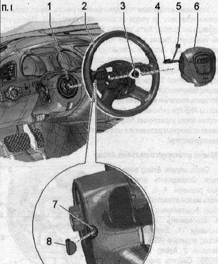
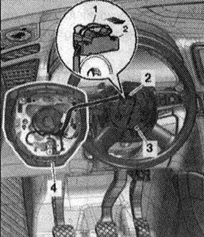
I 1. Used steering column "J527" with flat spring-shaped conductive element for Airbag and slip ring "F138" and steering wheel angle sensor "G85"; 2. Steering wheel; 3. Bolt; 4. Electrical connector for driver's Airbag squib "N95" and driver's Airbag squib 2 "N₂50". Replace; 5. Electrical connector for multifunction steering wheel option. Replace; 6. Airbag on the driver's side with squib 1 Airbag driver "N95" and squib 2 Airbag driver "N₂50"; 7. Bolt. 2 pcs. 7 Nm; 8. Cap 2 pcs. For driver's Airbag bolt
Removal Airbag with pyropatron "N95" and "N₂50"
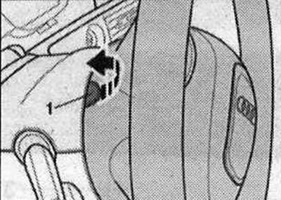
Set the steering wheel as far back as possible, using the full range of adjustment of the steering column adjuster. Turn on the ignition. Disconnect the battery ground cable with the ignition on. Turn the steering wheel so that the protective cap "1" on the back of the steering wheel points straight up (12 o'clock position). Peel off the upper cover of the steering column switch module near the Airbag bolt connection together with the adhesive tape to avoid damaging the surfaces. Press the "arrow" cap.
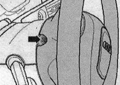
Unscrew the bolt "arrow" of the front passenger Airbag. Turn the steering wheel 180° and perform all work on the other side of the steering wheel.
Return the steering wheel to the center position (wheels in straight ahead position). Partially remove the front passenger airbag from the steering wheel. Pull the fuse of the connector "arrow" until it stops. This releases the locking of the electrical connector "2" and it can be removed. Version complete with multifunction steering wheel and Tiptronic steering wheel: disconnect the connector "3". Remove Airbag "4".
Installation
Install in reverse order, making sure that the electrical connectors are inserted as far as they will go and that they audibly engage. Make sure that the wires are not pinched. Connect the plug connector of the flat spring-shaped conductive element with the airbag socket and the slip ring. Place the driver's airbag module in the steering wheel. Tighten the 2 screws "arrow" to secure the driver's airbag module by approx. 2 turns. Press the horn 3 times to achieve an even gap. Do not touch the airbag any more. Tighten the screws "arrow". Insert the caps into the grooves on the steering wheel. Connect the battery ground cable with the ignition on. Query the fault memory of the airbag control unit and clear it, as fault messages may be entered into it when the plug connectors are disconnected.