
To obtain the required air temperature, fresh air is cooled by passing through the evaporator or, respectively, heated by passing through the heater radiator, and in vehicles with a TDI engine through an additional heating element.
The heat generated by the engine is transferred by the coolant to the heater radiator located in the passenger compartment. The air flow supplied by the ventilation system passes through the radiator and is heated by the heat of the engine coolant flowing inside the radiator. On vehicles with a TDI engine, due to its low heat output, an additional electric heater is installed, which heats the coolant if necessary.
Air conditioning is affected by the ratio of cold and warm air components mixed depending on the position of the corresponding flaps. All flaps are driven by small electric motors.
The body ventilation is provided by forming a through air flow. Fresh air enters the car through the air intake located in front of the windshield. The air flow goes out through the exhaust channels located under the rear bumper.
To prevent fresh air from entering the car interior, there is an air recirculation mode.
Operation of the air conditioner
The air conditioning system removes excess heat and moisture from the passenger compartment in accordance with basic physical principles. The refrigerant (R 134 a), circulating as a liquid in the high-pressure section of the system, evaporates and turns into a gas in the low-pressure section. When the gas expands, cooling occurs, accompanied by the removal of heat from the air supplied by the fan to the passenger compartment and a decrease in its temperature. Then, as it passes through the condenser, the refrigerant gives off the absorbed heat to the surrounding air. The heat removal cycle continues indefinitely as the refrigerant circulates in a closed circuit. Moisture is removed from the air supplied to the passenger compartment due to condensation on the evaporator of the refrigeration chamber.
The cooling intensity depends on the set temperature and the fan performance. Regulation is carried out by smoothly changing the fan speed depending on the temperature difference between the set temperature and the temperature in the car.
The air conditioning system uses a solar sensor located in the center of the instrument panel, under the windshield. When intense solar radiation occurs, the sensor increases the fan speed and the air flow supplied to the car's interior.
Electronic control is integrated into the air conditioner control panel.
Attention. Repairs to the air conditioner refrigerant circuit are not provided. These works must be carried out at a service station.
Safety instructions
- The air conditioning system must be serviced only by trained technical personnel who are trained in safe operating practices using the proper equipment, observing depressurization rules, and are familiar with the methods of collecting and storing automotive refrigerant.
- It is not recommended to open the air conditioner refrigerant circuit, as the refrigerant may cause frostbite when in contact with the skin.
- If the refrigerant comes into contact with your skin, immediately wash the affected area with cold water for at least 15 minutes. Immediately contact a doctor or medical facility. Self-medication is not allowed.
- The gaseous refrigerant is heavier than air and should collect relatively quickly below, for example, under a car. The refrigerant evaporates quickly, reducing oxygen availability and making breathing difficult. Work should be carried out in a well-ventilated area.
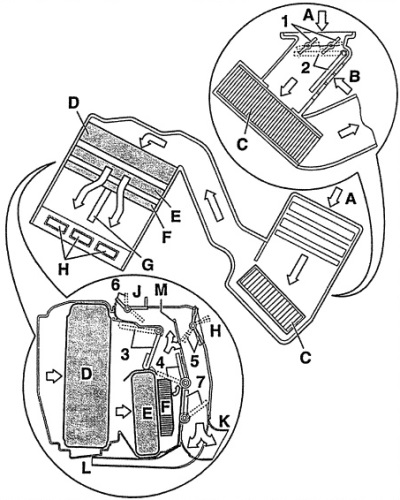
Fig. 13.1. Main elements of the air conditioning system
A - dust and pollen filter
B - front passenger legroom,
C - channel for fresh air,
D - evaporator,
E - radiator (heat exchanger) heater,
F - additional heating element,
G - driver and front passenger space,
H - to the nozzle in the instrument panel,
J - to the nozzle under the windshield,
K - to the nozzle in the rear passenger footwell,
L - to the nozzle in the footwell,
M - wire mesh
1 - air flow adjustment flaps,
2 - fresh air supply damper,
3 - air temperature change damper 1,
One on each side of the driver and front passenger.
4 - air temperature change damper 2,
One on each side of the driver and front passenger.
5 - central valve,
6 - heater flap,
7 - footwell flap.
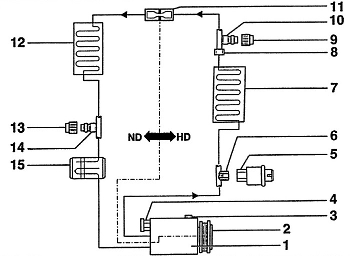
Fig. 13.2. Air conditioning system diagram
1 - compressor,
2 - electromagnetic clutch,
3 - oil drain plug,
4 - excess pressure valve,
5 - push-button switch for air conditioner and electromagnetic clutch,
6 - connection with valve,
7 - capacitor,
8 - screwing into the refrigerant line,
9 - cap,
10 - service connection,
On the high pressure side.
11 - throttle assembly,
12 - evaporator,
13 - cap,
14 - service connection,
On the low pressure side.
15 - collecting container,
HD - high pressure side,
ND - low pressure side.
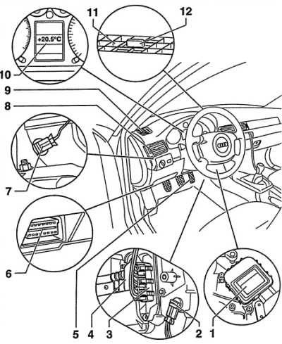
Fig. 13.3. Location of air conditioning system elements in the vehicle interior on the driver's side
1 - actuator motor for temperature control flap on the left side,
2 - outlet air temperature sensor,
In the footwell.
3 - additional heating element,
Only for vehicles with TDI engine.
4 - heat exchanger,
5 - Kick-Down switch,
Only for vehicles with automatic transmission. Depending on the vehicle speed and desired acceleration, the air conditioning solenoid valve can be switched off by the engine control unit.
6 - diagnostic connector,
7 - left outlet air temperature sensor,
8 - left ventilation nozzles,
9 - nozzles for defrosting glass on the left side,
10 - outside temperature indicator
11 - windshield defrosting nozzles,
12 - solar sensor,
To control the operation of the air conditioner depending on the amount of solar radiation.
Note: Since 9/98 the air conditioning system has been slightly modified.
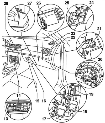
Fig. 13.4. Location of air conditioning system components in the vehicle interior on the front passenger side
13 - control panel,
The indicator and control buttons are illuminated by LEDs that cannot be replaced.
14 - air temperature sensor in the car interior,
15 - evaporator,
16 - nozzle,
17 - central damper actuator motor,
18 - actuator motor of the right temperature flap,
19 - heater flap actuator motor
20 - fresh air supply fan,
21 - right sensor of temperature of air entering the cabin,
22 - right ventilation nozzles,
23 - glass defrosting nozzles on the right side,
24 - fresh air temperature sensor,
25 - pressure valve actuator,
26 - fan controller,
27 - water condensate collector,
28 - medium ventilation nozzles
[The original version of the article is posted on the website AUDIMANUAL.RU]