
Table of contents: Removal ↓ Installation ↓
Removal
Remove the door trim.
Disconnect the electrical connectors connecting the front door to the A-pillar.
Remove the corrugated protective cover between the door and the A-pillar.
Remove all wires from the front pillar.
Using a T45 screwdriver, loosen the door mounting bolts on the upper and lower hinges and remove the door.
Disconnect and remove the electrical wires.
Using a fine-tip marker, mark the position of the door frame on the door.
Remove bolts 3, 9, 6 and 4 (fig. 12.29) and lift the door frame up.
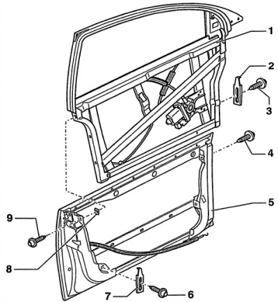
Fig. 12.29. Front door/front door frame
1 - front door frame,
2 - adjustment plate,
3 - bolt, 30 Nm,
4 - bolt, 40 Nm,
5 - front door,
6 - bolt, 30 Nm,
7 - adjustment plate,
8 - lining, self-adhesive.
9 - bolt, 30 Nm
Installation
Adjust the door.
In accordance with the previously applied marks, install the door frame and lightly secure it. To do this, tighten bolts 3, 4, 6, 9 (fig. 12.29), as well as the adjusting key 2 and 7. The adjusting plate must always be installed.
By changing the position of plate 6 (fig. 12.29) you can adjust the tilt of the door in the area of the middle pillar.
If the adjustment area of the plate is not sufficient, a larger washer must be placed under it. Never use two plates in the same place.
Close the door and check the adjustment again. If necessary, adjust the position of the door frame.
Tighten the bolts in the following order: 3, 9, 6 and 4 (fig. 12.29).
[A link to the original source is available on the website Audimanual.ru]