
Table of contents: Splitter 2 for terminal 30 "TV22"… ↓ Splitter 2 for terminal 30 "TV22"… ↓ Relay ↓ 3-section relay and fuse box ↓ 6-pin junction box on the A-pillar… ↓ 6-pin junction box on the A-pillar… ↓ Relay and fuse box with on-board… ↓ Relay and fuse box with on-board… ↓ 3-section relay and fuse box ↓ Relay/fuse box B "SB" ↓
Splitter 2 for terminal 30 "TV22" with a socket for starting the engine from an external source of starter current "U6" until October 2011
Installation location: in the engine compartment - in the center of the water drain box.
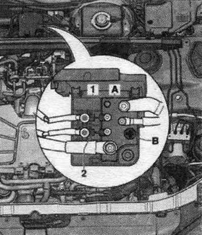
A. Splitter 2 terminals 30 "TV22".
B. Socket for starting from an external power source "U6".
1. Fuse 1 (30) "S204".
2. Fuse 2 (30) "S205".
Fuses on the splitter 2 terminals 30 "TV22" with a socket for starting the engine from an external source "U6"
| Number | Designation on the electrical circuit | Nominal value | Function/component | Terminal |
| 1 | Fuse 1 (30) "S204" | 40 A 60 A | Control system. 400 W fan Control system. 600 W fan | 30 |
| 2 | Fuse 2 (30) "S205" | 40 A | 400W Fan Control | 30 |
Splitter 2 for terminal 30 "TV22" with socket for starting the engine from an external source "U6" since November 2011
Installation location for vehicles since November 2011: in the engine compartment - in the center of the water drain box.
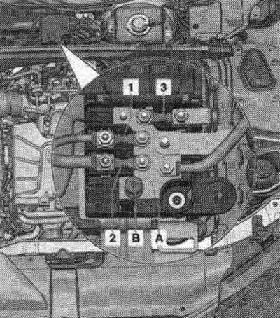
A. Splitter 2 terminals 30 "TV22".
B. Socket for starting from an external power source "U6".
1. Fuse 1 (30) "S204".
2. Fuse 2 (30) "S205".
3. Fuse 3 (30) "S206".
Fuses on the splitter 2 terminals 30 "TV22" with a socket for starting the engine from an external source "U6"
| Number | Designation on the electrical circuit | Nominal value | Function/component | Terminal |
| 1 | Fuse 1 (30) "S204" | 40 A 60 A | Control system. 400 W fan Control system. 600 W fan | 30 |
| 2 | Fuse 2 (30) "S205" | 40 A | 400W Fan Control | 30 |
Relay
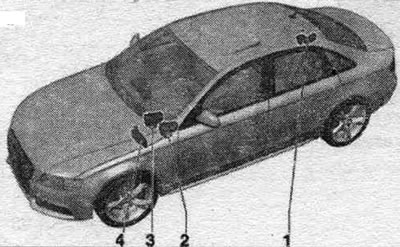
1. Relay box/fuse box F "SF": Components: "J9", "J84", "J807".
1. Battery isolation relay "J7"; Installation location: in the spare wheel niche, next to the second battery.
2. Relay and fuse box with used on-board network "J519": Units: "J160", "J318", "J329", "J413", "J601", "J608", "J910".
3. 3-section relay and fuse box: Units: "J359", "J360", "J604".
4. Relay/fuse box B "SB": Units: "J17", "J53", "J151", "J179". "J271", "J299", "J317", "J496", J695-, "J696", "J757". "J832". "J976".
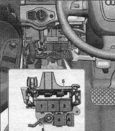
3-section relay and fuse box
The location of the 3-pin relay/fuse box for left-hand drive vehicles is under the dashboard. on the driver's side, on the relay and fuse box with a used on-board network "J519" and a threaded connection.
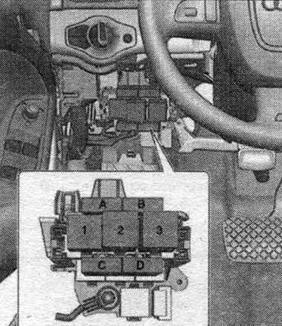
C. Additional fuse. heater "S126" 40A.
D. Fuse 2 additional heater "S328" 60 A.
6-pin junction box on the A-pillar on the driver's side
The installation location of the 6-pin switching unit on the A-pillar on the driver's side, for left-hand drive vehicles: on the A-pillar in the driver's footwell, behind the side trim.
F. Thermal fuse 1 front seat adjuster. passage. "S46", 15 A.
G. Thermal fuse 1 driver's seat adjuster. "S44".
6-pin junction box on the A-pillar on the front passenger side
Installation location of the 6-pin switching block on pillar A on the front side. passenger compartment, for left-hand drive vehicles: on the A-pillar in the front footwell. passage, behind the side paneling.
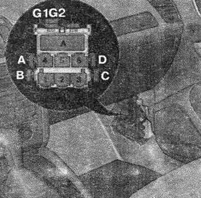
Relay and fuse box with on-board power supply control unit "J519"
The location of the used relay/fuse box "J519" for left-hand drive vehicles is under the front dashboard on the driver's side.
A. Fuse 1 used ABS "S123" 40 A.
Relay and fuse box with on-board power supply control unit "J519"
The location of the relay/fuse box with the used on-board network "J519" is under the front panel on the driver's side.

1. Not used.
2. Circulation pump relay "J160".
2. Horn relay "J413".
2. Vacuum pump relay "J318".
2. Relay of interior rear mirror. type with automatic dimming function "J910".
3. Power relay cl. 15. J329-.
4. Used remote control. anti-theft taxi alarm "J601".
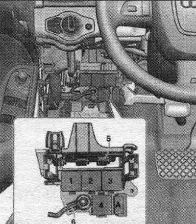
3-section relay and fuse box
The location of the 3-pin relay/fuse box for left-hand drive vehicles is under the dashboard. on the driver's side, on the relay and fuse box with a used on-board network "J519" and a threaded connection.
1. Used additional air heater "J604".
2. Low power heating relay "J359".
3. High power heating relay "J360".
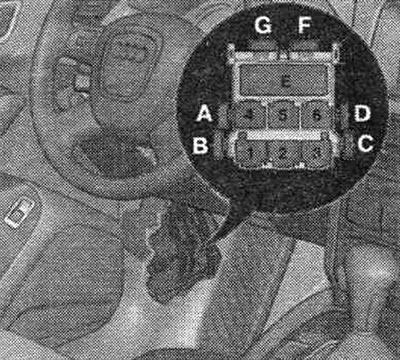
Relay/fuse box B "SB"
The location of the B "SB" fuse/relay box for left-hand drive vehicles is in the junction box of the water drain box on the driver's side.
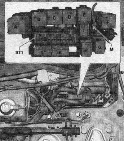
A. Used automatic glow plug system "J179".
A. Engine component power supply relay "J757".
B. Starter relay "J53".
B. Relay 2 starter "J695".
C. Secondary air pump relay "J299".
D. Power relay cl. 30 "J317".
D. System power relay. Motronic "J271".
E. Fuel relay pump "J17".
E. Additional fuel pump relay "J832".
E. Coolant recirculation relay after engine shutdown "J151".
E. Relay of additional pump of the system. cooling "J496".
E. Gearbox cooling circuit relay "J696".
E. Engine component power supply relay 2 "J976".
F. is not used.