
Repair Chevrolet Repair Toyota Repair Honda Repair AvtoVAZ Repair Mercedes-Benz Repair BMW Repair Opel
Home  |  Contacts  |  Sitemap  |    
English Русский
Български
Беларускі
Український
Српски
Hrvatski
Română
Polski
Slovenský
Magyar
AudiManual.ru


  • AUDI 80
  • AUDI 100
  • AUDI A3
  • AUDI A4
  • AUDI A6
  • AUDI A8
  • AUDI Q
  • OTHER
  • ARTICLES
B4 (1991-1996) B3 (1986-1991) B3 (1986-1991, petrol) B2 (1979-1986)

Removal and installation of indicator devices and control lamps (Audi 80 B3)

  • Home
  • Audi 80
  • B3 (1986-1991)
  • Electrical equipment
  • Lighting and appliances
  • Removal and installation of indicator devices and control lamps
            0
Table of contents: Removal ↓ Installation ↓
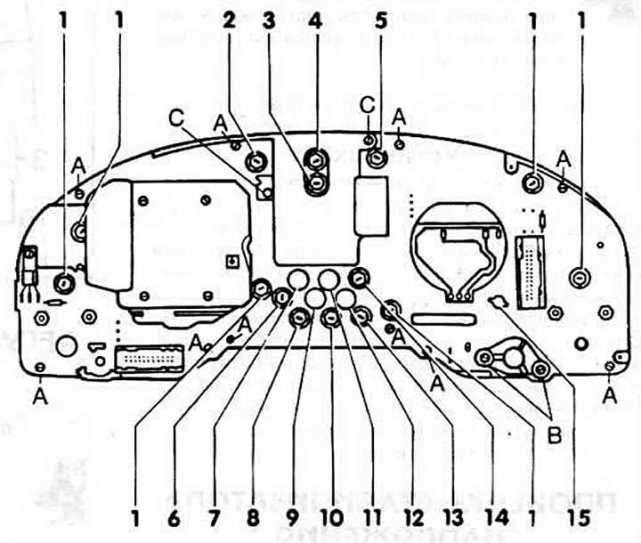
1.2W lamps for:

1.2W lamps for:
1 - dashboard set
2 - right turn signal
3 - brake fluid
4 - coolant temperature
5 - left turn signal
6 - high beam
7 - functional faults of the engine electrical equipment/idle speed control
8 - emergency alarm
9 - anti-lock braking system (ABS)
10 - handbrake
11 - Trailer direction indicators
12 - Diesel preheating/Air damper drive for carburetor engine
13 - oil pressure
14 - battery charge control, 2 W
15 - digital clock
A, B, C - PCB mounting screws


Removal


Remove the instrument panel and place it on a clean soft cloth. Be careful not to scratch the protective glass.

Turn the socket with the burnt-out lamp to the left with your hand or a narrow screwdriver and remove it.

Replace the lamp with the socket.

Unscrew the dimmer switch "B" of the instrument panel lighting and remove it.

Unscrew the two "C" bolts of the AUTO-CHECK self-monitoring system cover.

Unscrew "A" and remove the printed circuit board.

Note: When removing the printed circuit board, the pin for adjusting the fuel gauge will fall out. It is recommended to write down the indicator reading, otherwise it will have to be adjusted again. In this case, lightly insert the rubber pin into the guide shaft so that it can be easily removed in the installed state.


Unscrew the devices from the printed circuit board.

Installation


Screw the devices to the printed circuit board.

Insert and screw the printed circuit board. At the same time, insert the fuel gauge pin so that the arrow can be moved in both directions. Insert the rubber cap not completely into the quotation pin.

Screw on the cover of the AUTO-SNAP self-monitoring system.

Insert and screw in the instrument panel dimmer, don't forget the washer.

Install the instrument panel kit.

Adjust the fuel level indicator.

Check the operation of the devices.
The article was checked by auto expert Elisey Ermolaev
This article is available at russian, bulgarian, belarusian, ukrainian, serbian, croatian, romanian, polish, slovak, hungarian

Share information:
Previous articles
Audi 80 B3: Lighting and appliances
Next articles

Removal and installation the steering wheel switch
Removal and installation the instrument panel
Dashboard
Tail light bulb
Checking the voltage stabilizer
Adjusting the fuel gauge
Checking the speedometer sensor
Removal and installation the radio


Similar articles on other Audi car models:
Control lamps Audi 100 C3 (1982-1990, diesel)
Control and measuring devices. Warning and diagnostic systems Audi A3 Type 8L (1996-2003)
Checking control instruments and lamps Audi A4 B5 (1994-2001, petrol)
Wiring diagram of the instrument cluster display, control lamps,… Audi A6 C5 (1997-2004)
Air Conditioning Control Audi A8 D2 (1994-2002)
Control devices Audi Q5 Type 8R (2008-2017)
Connection plan for the boost pressure control system Audi A2 (1999-2005)
Link to this page in different formats


Visitor comments

No comments yet


How much will 33 + 19 =


80(B4, 1991-1996) 
  • General information
  • User manual
  • Maintenance
  • Troubleshooting
  • Power unit
  • Engine
  • Cooling system
  • Heating and ventilation
  • Petrol injection
  • Diesel fuel system
  • Fuel system
  • Exhaust systems
  • Ignition system
  • Transmission
  • Clutch
  • Car gearbox
  • Chassis
  • Brake system
  • Suspension and steering wheel
  • Body
  • Body and trim
  • Electrical equipment
  • Electrical system
  • Electrical circuits
 
80(B3, 1986-1991) 
  • General information
  • Repair characteristics
  • Maintenance
  • Power unit
  • Gasoline engine
  • Diesel engine
  • Engine lubrication system
  • Fuel system (gasoline)
  • Injection system (gasoline)
  • Fuel system (diesel)
  • Ignition system
  • Cooling system
  • Heater
  • Exhaust system
  • Transmission
  • Clutch and gearbox
  • Chassis
  • Steering
  • Brake system
  • Car suspension
  • Body
  • Body elements
  • Electrical equipment
  • Power devices
  • Lighting and appliances
  • Electrical circuits
 
80(B3, 1986-1991, petrol) 
  • General information
  • User manual
  • Maintenance
  • Power unit
  • Engine 4-cylinder
  • Engine 5-cylinder
  • Cooling system
  • Fuel and exhaust systems
  • Ignition system
  • Transmission
  • Clutch
  • Mechanical transmission
  • Automatic transmission
  • Drive shafts
  • Chassis
  • Brake system
  • Suspension
  • Steering
  • Body
  • Exterior
  • Interior
  • Electrical equipment
  • Equipment and devices
  • Electrical circuits
 
80(B2, 1979-1986) 
  • General information
  • User manual
  • Power unit
  • Engine FZ
  • Engine EP, YP, YZ, DT, DS, DZ
  • Transmission
  • Clutch
  • 4 speed gearbox
  • 5 speed gearbox
  • Front wheel drive
  • Chassis
  • Front suspension
  • Rear suspension
  • Steering
  • Brake system
  • Electrical equipment
  • Equipment and devices
  • Electrical circuits
 
AudiManual.ru © 2017-2026 · Mobile version · Feedback · Sitemap: EN BG BY UA RS HR RO PL SK HU · Site search · News and articles
80 B2 · 80 B3 petrol · 80 B3 · 80 B4 · 100 C3 diesel · 100 C3 petrol · 100 C3 · 100 C4 petrol · 100 C4 · A3 Type 8L · A4 B5 petrol · A4 B5 · A4 B6 petrol · A4 B6 · A4 B7 · A4 B8 · A6 C4 · A6 C5 · A6 C5 Allroad · A8 D2 · Q5 Type 8R · Q7 Typ 4L · Audi A2 ·
This site uses cookies 🍪. Click the button to accept this fact.