



Table of contents: Location of fuses ↓ Relay location ↓ Connectors on the bottom side of the… ↓ Removal the plugs ↓ Location of the relay on the… ↓ Places of installation of electronic… ↓
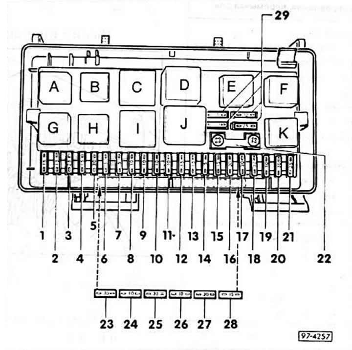
Location of fuses
The location of the fuses depends on the model and year of the car. It can be found in the car manual.
no. — Amp. — Consumer
1 - 15 - Fog lights/Rear fog lights
2 — 15 — Hazard warning lights, direction indicators (up to 4/87).,
3 - 25 - Signal, brake lights, speed control system (brake and clutch pedal).
4 - 15 - Clock, trunk light, interior light, power mirror, socket/cigarette lighter, trip computer, reading light, automatic air conditioning.
5 — 30 — Radiator fan 4-cylinder engine (all-wheel drive).
6 - 5 - Side and parking light on the right
7 — 5 — Side and parking light on the left
8 - 10 - High beam on the right, high beam indicator lamp.
9 - 10 - High beam left
10 - 10 - Low beam right
11 - 10 - Low beam on the left.
12 — 15 — Switch panel kit, reversing lights, self-monitoring system. Speed control system control unit. ABS, differential lock, trip computer, idle speed control, throttle position sensor, time control device electronic thermal switch, independent fan operation control unit.
13 - 15 - Fuel pump, heating regulator.
14 — 5 — License plate light, engine compartment light, glove compartment light.
15 - 25 - Windscreen wiper, thermal switch, radiator fan, air conditioner, direction indicator (from 5/870).
16 — 30 — Rear window heating, mirror heating.
17 — 30 — Heater fan, air conditioner.
18 — 5 — Electric adjustment of exterior mirrors.
19 - 10 - Central lock.
20 - 30 - Radiator fan 1st stage, independent fan operation - 4-cyl. engine.
21 — 25 — Rear cigarette lighter.
22 — 80 — Diesel preheating system.
23 — 30 — Electric adjustment of the right front seat, Memory-Sitz control unit.
24 — 10 — KE-Jetronic control unit.
24 — 30 — Heated seats.
26 – 10 – Taxi, police
27 — 20 — Electric sunroof.
28 — 15 — KE-Jetronic control unit.
29 — 5/10 (25/30) — Spare fuses.
Relay location
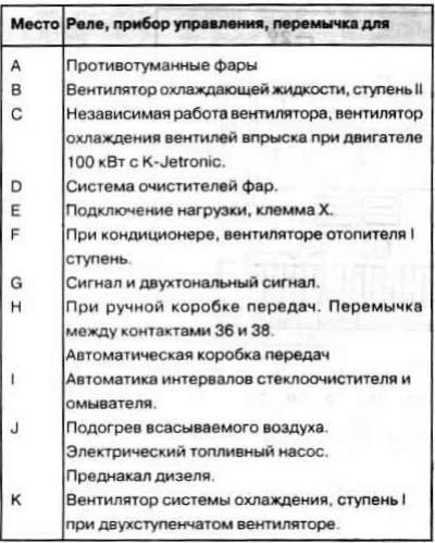
Note: The letter designation of the relay in Fig. 97-4257 does not match the designation of the connectors on the back of the relay board.
Connectors on the bottom side of the relay board
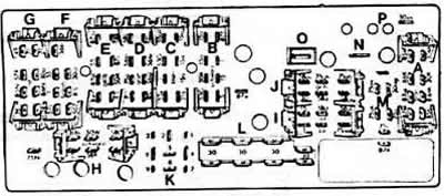
Multi-pin plug for / (color)
A - air conditioner harness (gray)
B - front right harness (black)
C - Instrument cluster harness (blue)
D - front left harness (green)
E - front left harness (yellow)
F - Instrument cluster harness (brown)
G - Instrument cluster harness (red)
H - rear harness (black)
I - Instrument cluster harness (red)
J - Instrument cluster harness (yellow)
K - relay socket 3 (black)
L - plug-terminal 30
M - plug for M-version
N - glow plug plug
O - plug - intake air heating
P - fuse plug No.20
Removal the plugs
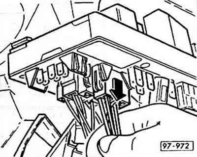
To remove the plug from the relay board, firmly grasp the plug body and pull it out. If this does not work, you can additionally pull on the wires.
Location of the relay on the additional board
The additional relay board is located in the passenger compartment behind the left footwell trim.
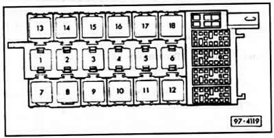
Place / Relay, control device, jumper for
1 Anti-lock braking system (ABS)
2 Emergency buzzer for radio and parking light.
3 Time delay of interior lighting.
4 Magnetic clutch (air conditioner).
5 Rear window washer.
Oil cooler fan, only with 59 kW turbodiesel and trailer.
6 Oil pressure control.
Self-monitoring system indicator lamp.
7, 8 Signaling system 1 (taxi).
9 Thermal relay³ electric windows, electric sunroof, seat adjustment.
10 Idle speed control², 5 cyl. engine.
Digital idle speed control 1, only 85 kW engine with K-Jetronic.
Cooling system pump, turbodiesel.
11 Idle speed control2.5 cyl. engine.
Digital idle speed control, only 85 kW engine with K-Jetron. Increased idle speed, 66 kW engine with KE-Jetronic and 82 kW engine with K-Jetronic.
Automatic glow plug timing for turbodiesel.
12 Idle speed control², 5 cyl. engine.
Automatic glow plug timing for turbodiesel.
13, 14 Heated driver's seat.
15 Electric sunroof with electric window¹.
Electric sunroof only.
16 Electric sunroof with electric window¹.
17 Distributor adapter terminal 75S.
18 Daytime Driving Light4.
Light of city driving4.
Catalyst control4.
Independent fan operation4.
1) The control device occupies 2 relay sockets.
2) The control device occupies 3 relay sockets.
3) The automatic fuse switches off when overloaded and switches back on after a while.
4) For export only.
Places of installation of electronic control devices
Powerful key cascade of electronic ignition VEZ: on the ignition coil in the engine compartment.
Glow Plug Relay (turbodiesel only) in the engine compartment next to the relay board.
Transistor ignition system switch TSZ) (not for VEZ): behind the trim in the footwell, front left.
Direction indicator switch: on the left behind the lower edge of the instrument panel. Trip computer: behind the instrument panel. KE-Jetronic control unit: behind the glove compartment, between the front wall and the fan box.
Speed control system control unit: behind the glove compartment, on top under the instrument panel.
Control unit for VEZ and height sensor for KE-Jetronic: behind the trim on the right in the footwell.
Instrument Lighting Amplifier (only for vehicles with additional devices): behind the heater control panel.
Electric seat adjustment control unit: under the driver's seat.
For all-wheel drive vehicles, the control unit for the differential lock and the longitudinal acceleration sensor-switch for ABS are located in the center under the rear seat.
Control unit for anti-lock braking system (ABS): on the left under the rear seat.
Antenna amplifier for retractable antenna: in the passenger compartment behind the left trim of the rear pillar of the body.
Lamp control device (only with AUTO CHECK system): on the side behind the left trunk trim.
Central locking motor (pump): on the side behind the right trunk trim.
[The article was copied from the website AudiManual.ru]