



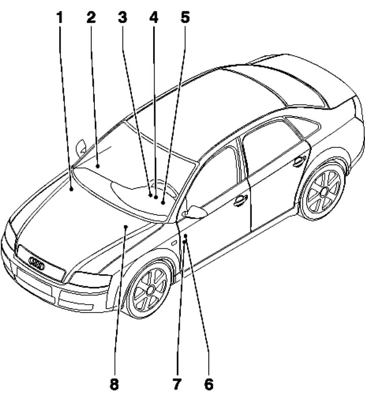
13.1. Location of relay and fuse mounting blocks 1. Fuse S88, at the positive terminal of the battery; 2. Fuse S46 in the junction box on the right A-pillar (see illustration 13.2); 3. Relays and fuses S126 and S328 in the 3-relay mounting block behind the instrument panel (see illustration 13.3); 4. Relays and fuses S37, S45, S87, S100, S184 and S280 in the 9-relay mounting block with the on-board power supply control unit, behind the instrument panel (see illustration 13.4); 5. Relays and fuses S42, S51, S123 and S214 in the 4-relay mounting block, behind the instrument panel (see illustration 13.5); 6. Relay (only for taxis and police) and fuses S1-S22, S223 and S244 in the fuse box, behind the left end cover of the instrument panel (see illustration 13.6); 7. Fuses of special models (taxi, police) in the instrument panel on the driver's side; 8. Relays and fuses in the mounting block for 4 relays, in the gutter (see illustration 13.7)

13.2. Connection block on the right A-pillar (below, behind the trim) E - Fuse (S46) for electric seat adjustment
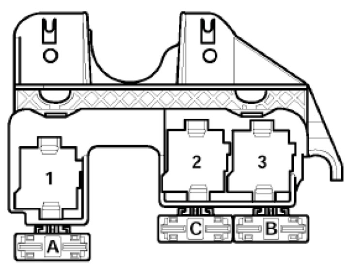
13.3. Mounting block for 3 relays behind the instrument panel (on the driver's side) 1. Control unit (J608) special models (educational, taxi); 2. Low heat output relay (J359); 3. Relay (J360) high heat output; A - Fuse (S62) for additional heater (models up to 2003.); B - Fuse (S126) No.1 additional heater; C - Fuse (S328) No.2 additional heater
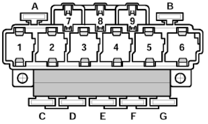
13.4. Mounting block for 9 relays with on-board power supply control unit, behind the instrument panel (on the driver's side), behind the holder for 3 relays 1. Relay (J17) fuel pump; 2. Servotronic control unit (J236); 3. Motor starter relay No.2 (J695) AUK/BKH/BNS B f; 4. AUK/BKH/BNS engine starter relay (J53) or vacuum booster relay (J569) on models with engines other than AUK/BKH up to 2005 model year; 5. Relay (J9) for heated glass; 6. Terminal X overflow relay (J59); 8. Relay (J4) 2-tone horn; A - Fuse (S100) overheating of the electric drive of the rear curtain; B - see "A" or fuse (S184) of socket #1 on training models; D - Fuse (S280) No.2 electric window lifter; E - Fuse (S45) No.2 overheating of the electric drive of the driver's seat; F - Fuse (S37) electric window drive; G - Trailer electrical equipment fuse (S87)
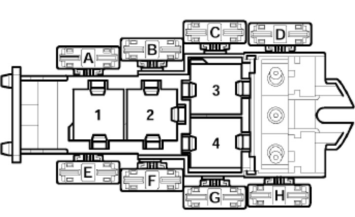
13.5. Mounting block for 4 relays with screw connection, behind the instrument panel (on the driver's side) 3. Relay No.1 (J662) for reducing engine power for training models; 4. Relay No.2 (J663) for reducing engine power for training models or control unit (J610) for the anti-theft system and hands-free communication; B - Repellent (additional equipment); E - Fuse (S51) on training models; F - Fuse (S51) on training models, or fuse (S42) for the engine cooling fan; G - Fuse (S214 or S42) engine cooling system fan; H - Fuse (S123) No.1 ABS control unit
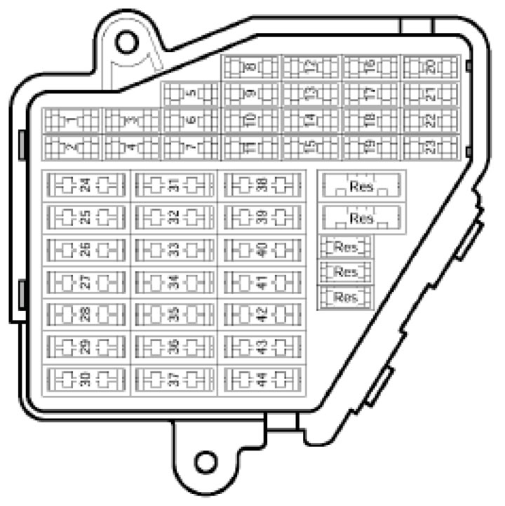
13.6. Fuses in the mounting block behind the right end cover of the instrument panel
Explanatory table for illustration 13.6
| Number in the mounting block | Designation on diagrams | Current, A | Chain | Terminal |
| 1 | S1 | 10 | Climate control unit (J255) | 30 |
| 2 | S2 | 5 | Footwell Lights: Front Left/Front Right/Rear Left/Rear Right (W9/W10/W45/W46) | 30 |
| 3 | S3 | 5 | Heating of left/right windscreen washer nozzle (Z20/Z21) | 75x |
| 4 | S4 | 5 | Cooling system fan control unit #1/#2 (J293/J671) | 87 |
| 5 | S5 | 10 | Rear curtain switch (E149), function selector switch No.2 (E272), manual gearshift mode switch (F189), engine oil level and temperature sensor (G226), rear curtain control unit (J262), navigation system with CD control unit (J401), parking assistance control unit (J446) | 15 |
| 6 | S6 | 5 | High pressure sensor (G65), air quality sensor (G238) | 15 |
| 7 | S7 | 10 | ESP switch (E132), D/B clutch/brake pedal position (F36/ F47), ABS control unit (J104) | 15 |
| 8 | S8 | 5 | Telephone Transceiver Module (R36), Mobile Phone Antenna Amplifier (R86) | 30 |
| 9 | S9 | 15 | Brake booster relay (J569) | 30 |
| 10 | S10 | 5 | Headlight range control (E102), headlight range control unit (J431), right headlight ignition unit (J668), left/right headlight range control motor (V48/V49) | 15 |
| 11 | S11 | 10 | SRS control unit (J234), seat occupied module (J706), airbag deactivation K/L (K145) | 15 |
| 12 | S12 | 10 | 16-pin black diagnostic connector (T16) | 30 |
| 13 | S13 | 10 | Steering column electronics control unit (J527) | 30 |
| 14 | S14 | 10 | D/W brake lights (F) | 30 |
| 15 | S15 | 10 | Control unit in instrument panel insert (J285), control unit for navigation system with CD (J401) | 30 |
| 16 | S16 | 5 | Switch (E284) and control unit (J530) for universal remote control | 15 |
| 17 | S17 | 10 | Rain and light sensor (G397), parking assistance control unit (J446), tyre inflation pressure monitor control unit (J502) | 30 |
| 18 | S18 | 5 | Left headlight turn signal motor (V318) | 15 |
| 19 | S19 | 15 | Left/Right Fog Light Bulb (L22/L23) | 55 |
| 20, 21 | S20, S21 | - | Free | - |
| 22 | S22 | 15 | Front left/right door control unit (J386/J387) | 30 |
| 23 | S223 | 15 | Rear left/right door control unit (J388/J389) | 30 |
| 24 | S224 | 20 | Central control unit for comfort systems (J393) | 30 |
| 25 | S225 | 30 | Fresh air supply fan control unit (L 26) | 30 |
| 26 | S226 | 30 | Rear window heating relay (E87) | 30 |
| 27 | S227 | 30 | Trailer Detection Unit (J345) | 30 |
| 28 | S228 | 20 (on the BNS - 30 engine) | Fuel system filling pump (G6) | 87 |
| 29 | S229 | - | Free | - |
| 30 | S230 | 20 | Sunroof Control Unit (J245) | 30 |
| 31 | S231 | 15 | Reversing light (F4), air mass meter (G70), light sensor (G399), AT control unit (J217), selector lever lock solenoid (N110), 16-pin diagnostic connector (T16), auto-dimming interior rearview mirror (Y7) | 15 |
| 32 | S232 | 15 | Trailer connector (U10) from 2006 model year | 75x |
| 33 | S233 | 15 (since 2005.02 - 20) | Cigarette lighter (U1) | 30 |
| 34 | S234 | 30 (since 2005.02 - 20) | 12V socket (U5) | 87 |
| 35 | S235 | 30 (since 2005.02 - 20) | Socket (U) | 30 |
| 36 | S236 | 30 | On-board power supply control unit (J519), rear window wiper motor (V12) | 75x |
| 37 | S237 | 30 | On-board power supply control unit (J519), headlight washer pump (V11) | 75x |
| 38 | S238 | 15 | Module No.1 of the transceiver in the interior mirror (G303), siren (H12), central control unit for comfort systems (J393) | 30 |
| 39 | S239 | 20 | Control unit for navigation system with CD (J401), unit for audio and navigation system (J503), radio (R), amplifier (R12), satellite radio (R146), 8-pin black radio connector (T8) | 30 |
| 40 | S240 | 25 | High/low frequency horn (H2/H7), 2-tone horn relay (J4) | 30 |
| 41 | S241 | 30 | Additional heater control unit (J364), additional heater remote control receiver (R64) | 30 |
| 42 | S242 | 25 | ABS control unit (L 04) | 30 |
| 43 | S243 | 15 | Air flow meter (G70), EGR potentiometer (G212), Simos ECM power supply relay (J363), engine components power supply relay (J757), EGR valve (N18) | 15 |
| 44 | S244 | 30 (up to model year 2005) or 35 (since model year 2006) | Climate control unit (J255) | 30 |

13.7. Mounting block for 4 relays in the gutter (using the example of BGB, BPG, BWE, BWT, BUL, BPJ, BYK engines) 1.2. Engine start enable relay (J217); 2. Relay (J271) power supply ECM Motronic; 3. Relay (J757) for power supply of engine components; A - Fuse (S282) engine electronics; B - Fuse No.3 (S345) engine electronics; C - ECM fuse (S102); D - Fuse No.1 (S131); E - Fuse No.2 (S344) engine electronics; G - Additional fuse (S286) AT