
Table of contents: Hub assembly ↓ Hub assembly holder ↓
1. The rear wheel hubs together with the wheel bearings form hub assemblies secured to their holders (see illustration).
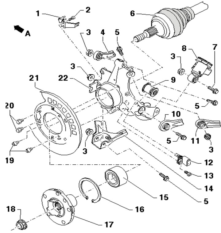
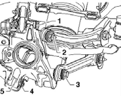
10.1. Details of installation of the rear suspension hub assembly and its holder:
Arrow A - Forward direction;
1 - Bracket;
2, 13, 20 - Bolt, 8 Nm;
3 - Self-locking nut, subject to replacement;
4 - Front upper control arm;
5 - Bolt, to be replaced, 150 Nm, then tighten to an angle of 90°;
6 - Drive shaft;
7 - Bolt, to be replaced, 90 Nm, then tighten to an angle of 90°;
8 - Suspension strut;
9 - Glued rubber bushing;
10 - Guide lever;
11 - Rear upper control arm;
12 - Rear wheel ABS sensor;
14 - Lower suspension arm;
15 - Wheel bearing;
16 - Retaining ring, gap facing down;
17 - Hub;
18 - Hub nut, self-locking, subject to replacement, 500 Nm;
19 - Bolt, 20 Nm;
21 - Brake mechanism shield;
22 - Hub assembly holder.
The bearing can only be removed after the hub has been removed.
Hub assembly
2. Remove the drive shaft (see Section 9).
3. Remove the caliper (1 in the illustration) brake mechanism (see Chapter 8) and tie the caliper to the brake line bracket (3) using wire (2).
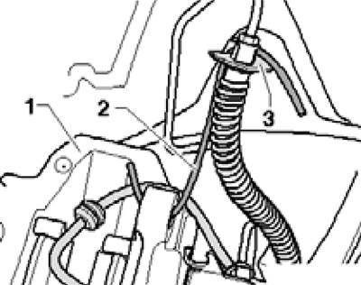
10.3. Suspended support.
Remove the brake disc (see Chapter 8).
4. Unscrew the bolt (3 in the illustration) and pull out the rear ABS wheel sensor (4).
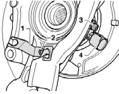
10.4. Bracket (1) and ABS sensor (2) on the hub assembly holder.
Disconnect the wiring harness from the bracket (2). Remove the parking brake cables from the hub assembly holder and remove the parking brake shoes (see Chapter 8).
5. Further actions are performed in the same way as the actions described in paragraphs 4-9 for the front hub assembly.
Hub assembly holder
6. Remove the drive shaft (see Section 9).
7. Insert a wooden block between the bottom (And in the illustration) and the rear upper control arm (B) to be able to press down the hub assembly carrier.
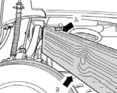
10.7. Installation of a wooden block.
8. Remove the bolt nut (see illustration).
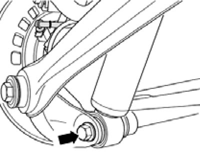
10.8. Bolt.
Using a block of wood, push the hub assembly retainer down just enough to remove the bolt. Remove the bolt.
9. Release the parking brake (see chapter 8), remove the hub assembly (see subsection above), and remove the brake shield (see Chapter 8).
10. Remove the bolts (1-4 in the illustration) and remove the hub assembly holder (5).
10.10. Wheel bearing fasteners.
11. Disconnect the rear ABS sensor connector (4 in illustration 10.4) and separate the wiring harness from the bracket (1). If the hub assembly holder is to be replaced, move the bracket and sensor to the new holder.
12. Installation is carried out in reverse order. Finally, check and adjust the rear wheel alignment angles (see Chapter 9).
[A link to the original source is available on the website AUDImanual.ru]