
Table of contents: Removal the glove box bracket ↓ Removal the central tube of the… ↓ Installation ↓ Removal the support bracket ↓ Installation ↓ Removal of left energy absorbing… ↓ Removal of the right energy… ↓ Removal the glove box bracket ↓ Installation ↓
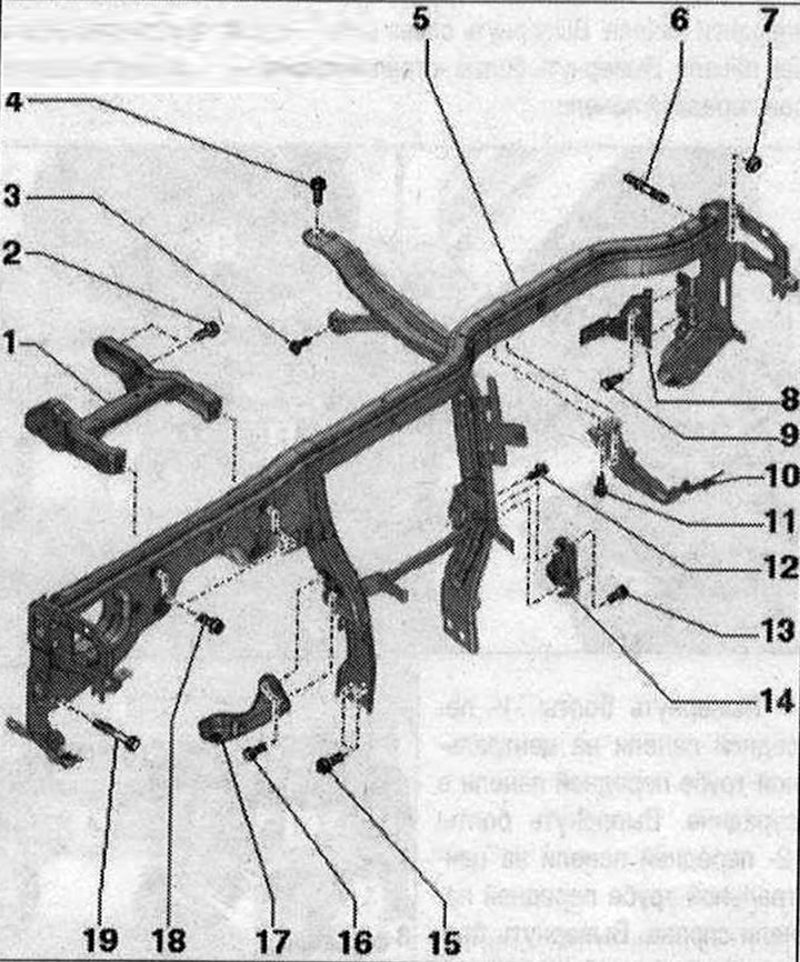
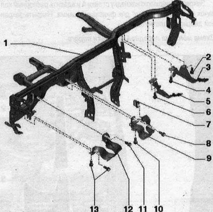
Front panel center tube 1. Support cushion; 2/15. Bolt. 4 pcs. 20 Nm; 3. Bolt 3.6 Nm; 4/19. Bolt. 20 Nm; 5. Central pipe for the front panel; 6. Threaded stud. 2 pcs. 20 N·m; 7. Nut. 2 pcs. 20 N·m. Replace after each removal; 8. Air intake box bracket; 9/11/13/16. Bolt. 2 pcs. 9 Nm; 10. Glove box bracket; 12. Bolt. 2 pcs. 3.6 Nm; 14. Glove box bracket; 17. Bracket for front panel trim; 18. Bolt. 2 pcs. 20 Nm
Removal the glove box bracket
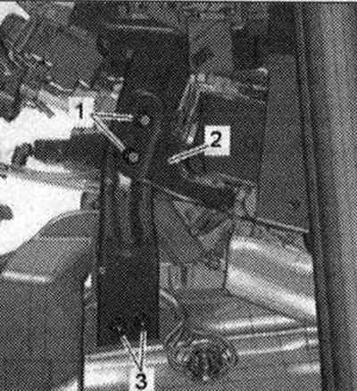
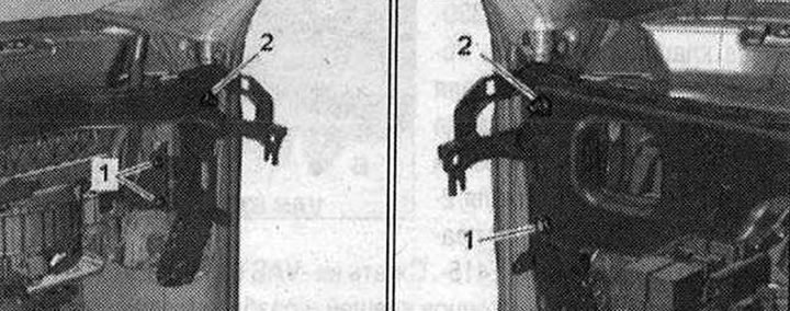
Remove the glove box. Unscrew the bolts "2". Disconnect and remove the support "1" of the glove box from the front panel.
Installation in reverse order.
Removal the central tube of the front panel
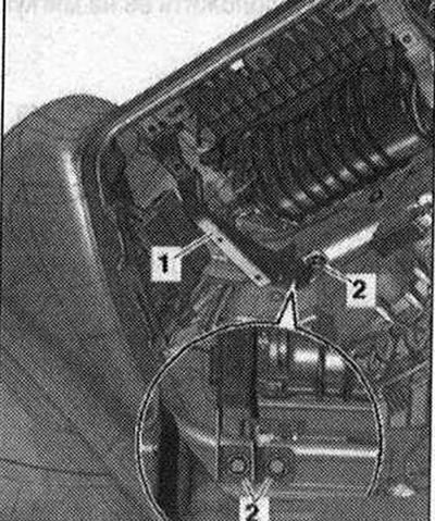
Remove the front panel. Unscrew the steering column from the central pipe and place it on the floor of the car. Unfasten the left air duct of the front panel deflector from the central pipe of the front panel. Remove the air duct of the front panel deflector on the right. Remove the fuse block C "SC" on the left and the fuse block D "SD" on the right from the central pipe of the front panel. Remove the data bus diagnostic interface "J533" and put it aside. Unscrew the bolts "1" on the left and right on the support of the central pipe and remove the bracket "2". Unscrew the bolts "3" on the left and right of the support of the central pipe.
Unscrew the bolts "1" of the air conditioner on the left and right side of the central tube support.
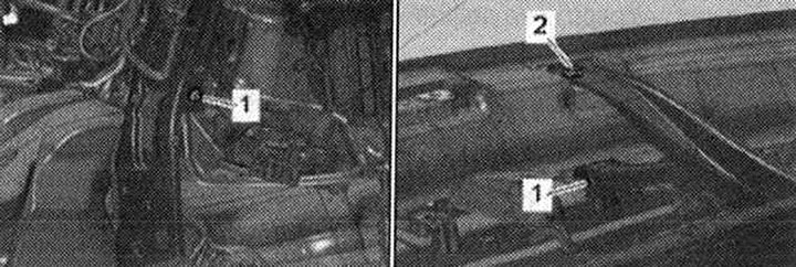
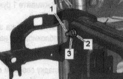
Remove the air duct of the middle defrost deflector. Unscrew bolt "1" of the air conditioner on the upper brace of the central tube of the front panel. Unscrew bolt "2" of the upper brace of the central tube of the front panel.
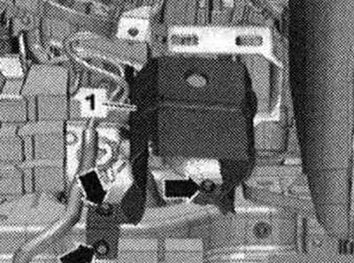
Unscrew the ground cable from the ground connection point on the left side of the tunnel wall and release it. Disconnect and release the plug connectors of the gas pedal module and the brake light switch. Remove the right front door sill trim. Disconnect the connectors to the plug block of the A-pillar on the left and right. Disconnect the plug connectors of the fresh air fan and release the wires. Unscrew bolts "1" securing the air intake box bracket to the central pipe of the front panel. Unscrew nut "2".
Unscrew bolt "1" and nut "2".
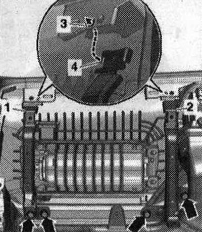
Lock 2 nuts "2" and "3" of the mounting screw "1" on the driver's side A-pillar and unscrew the mounting screw. Pull the central tube "1" of the driver's side front panel carefully upwards and unfasten it from the air conditioner "3", from the retaining clamps at the top "2" and bottom "4". Remove the central tube of the front panel of the front passenger side A-pillar from the mounting screw.
Pull the central tube of the front panel back, holding it by the upper part, carefully and pull it upward. Remove the central tube of the front panel from the car interior.
Installation
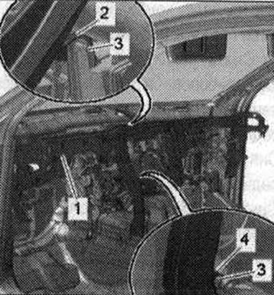
Carefully install the central tube "1" of the front panel into the body. Hang the central tube of the front panel on the air conditioning system "3" and the retaining clamps at the top "2" and bottom "4".
Place the central tube "4" of the front panel evenly on the A-pillar. Lock 2 nuts "2" and "3" on the set screw, screw in and tighten the set screw into the fastening "5" of the A-pillar on the driver's side. Screw the set screw in all the way so that the flange touches the fastenings of the A-pillar.
Tighten the left and right bolt and nuts of the central pipe of the front panel. Installation in the reverse order, while installing the steering column. Connect the battery ground cable with the ignition on.

Removal the support bracket
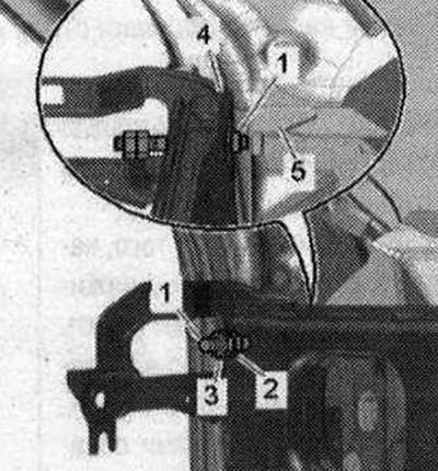
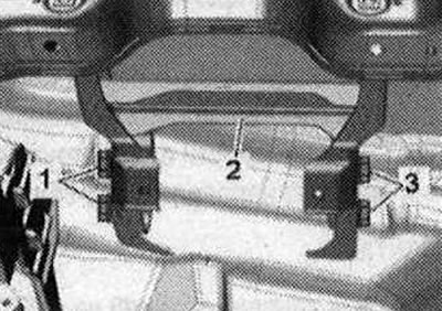
Remove the front panel deflector air duct on the left. Unscrew bolts "1" and "3" and remove the support bracket "2" downwards.
The figure shows the view with the steering column removed.
Installation
Installation in reverse order: The support bracket can only be positioned correctly when the center tube is installed. First screw the steering column with the support bracket to the center tube, then tighten the bolts "1" and "3" of the support bracket to the mount on the lower frame of the windshield.
Parts and components of the energy absorbing beam and glove box brackets. Depending on the kit or national market
1. Central pipe; 2/4/10/11. Bolt. 9 Nm; 3. Right glove box bracket; 5. Left glove box bracket; 6/13. Bolt. 2 pcs. 9 Nm; 7. The tip is mounted on the energy-absorbing bar "pos. 9"; 8. Bolt; 9. Right energy absorbing buffer; 12. Left energy absorbing buffer
Removal of left energy absorbing beam. Option for national markets
Remove the driver's side front panel trim. Unscrew the "arrow" bolts. Remove the left energy-absorbing bar "1" downwards.
Installation in reverse order.
Removal of the right energy absorbing beam. Option for national markets
Remove the driver's side front panel trim. Remove the driver's side front panel trim. Unscrew the "arrow" bolts. Remove the right energy-absorbing bar "1" downwards.
Installation in reverse order.
Removal the glove box bracket
Unscrew the "arrow" bolts. Remove the left "1" and right "2" glove box bracket.
Installation
Unscrew the "arrow" bolts. Remove the left "1" and right "2" glove box bracket.
Install both glove box brackets so that cover "4" is fixed in hole "3" on the front panel. Installation is in reverse order.