Repair Chevrolet Repair Toyota Repair Honda Repair AvtoVAZ Repair Mercedes-Benz Repair BMW Repair Opel
Home  |  Contacts  |  Sitemap  |    
English Русский
Български
Беларускі
Український
Српски
Hrvatski
Română
Polski
Slovenský
Magyar
AudiManual.ru


  • AUDI 80
  • AUDI 100
  • AUDI A3
  • AUDI A4
  • AUDI A6
  • AUDI A8
  • AUDI Q
  • OTHER
  • ARTICLES
Q7 Typ 4L (2005-2015, diesel) Q5 Type 8R (2008-2017)

Wing assembly diagram (Audi Q5-8R)

  • Home
  • Audi Q
  • Q5 Type 8R (2008-2017)
  • Body
  • Exterior
  • Wing assembly diagram
            0
Table of contents: Wing mount ↓ Wing strut ↓ Replace wing seal ↓ Removing the wing trim ↓
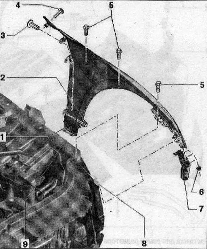
Wing assembly diagram

  • 1. Wing. Removal: remove the water collection channel. Remove the water drainage box lining. Remove the front bumper. Remove the headlight. Remove the wheel arch liner. Remove the wing end trim. Unscrew bolts "2"; "4" and nuts "7" and remove the wings. Installation: in reverse order.
  • 2-5. Bolt. 8 Nm
  • 6. Nut. 4 Nm
  • 7. Wing fastening
  • 8. Stretching

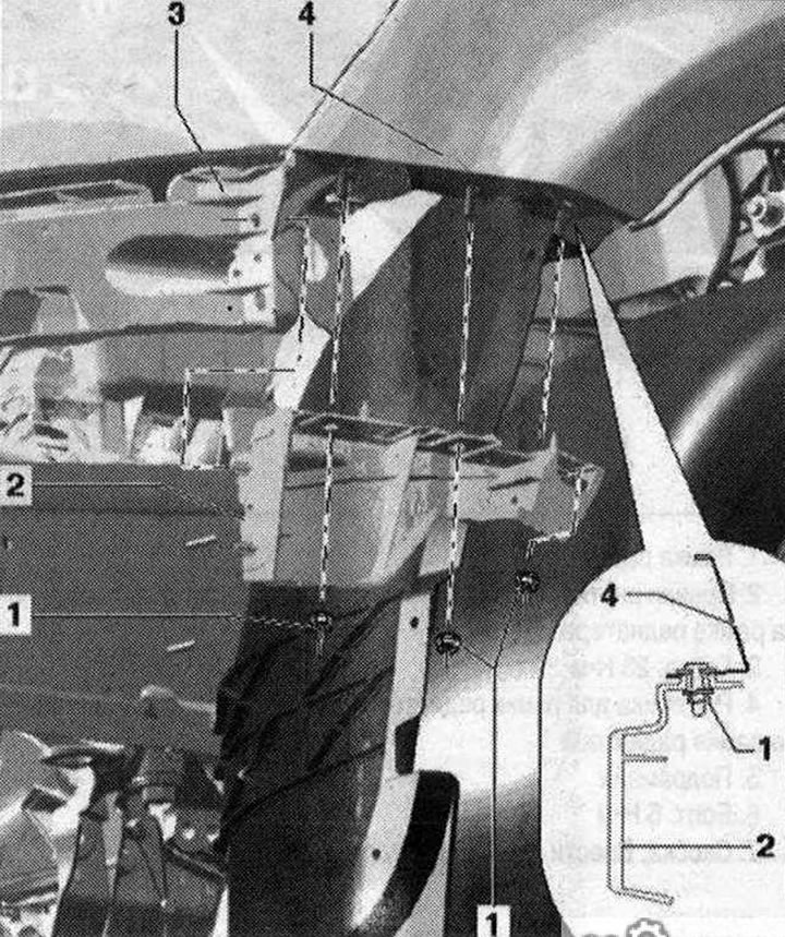
Wing mount


Wing mount

  • 1. Nut. 4 Nm
  • 2. Wing fastening
  • 3. Fastening the headlight
  • 4. Wing

Wing strut


Wing strut

  • 1. Stretching. Remove the bumper and move the fender liner to the side in the stretching area. To remove, unscrew the bolts "2"
  • 2. Wing bracket
  • 3. Bolt 10 Nm
  • 4. Wing
  • 5. Fastening the bumper cover
  • 6. Nut. 4 Nm
  • 7. Stretching


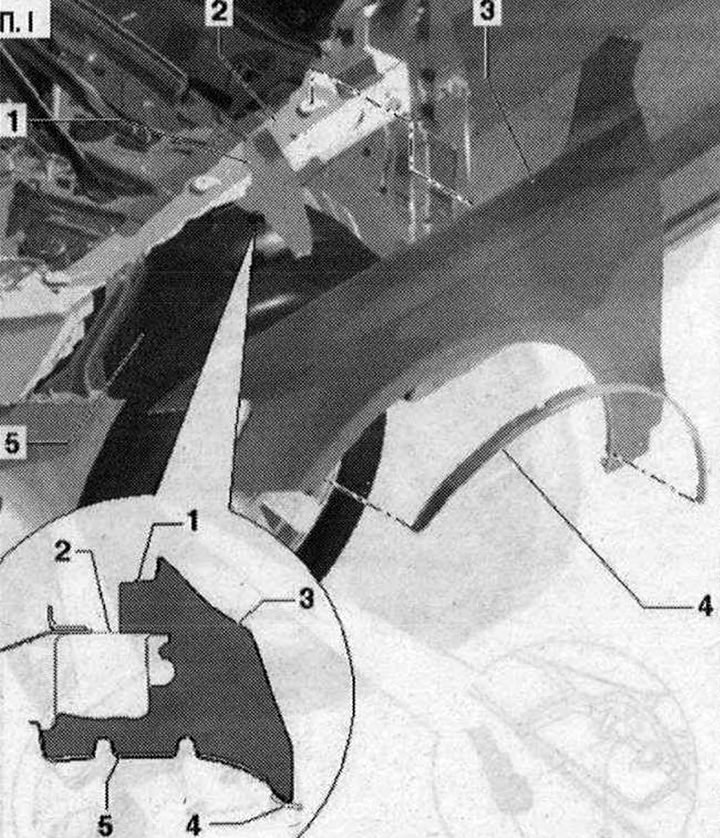
Replace wing seal


I 1. Gasket. Self-adhesive. Remove the protective film and install the seal on the wing bracket…

I 1. Gasket. Self-adhesive. Remove the protective film and install the seal on the wing bracket under the fender liner, as shown in the figure; 2. Wing bracket. Install the seal on the wing bracket between the fender liner and the inner side of the wing; 3. Wing; 4. Overlay. Pay attention to the difference in execution. The surfaces to be glued must be cleaned of dust and degreased. Remove the protective film, slide the cover on and press firmly


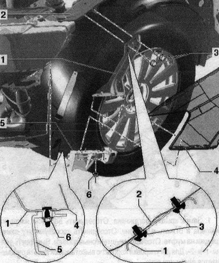
Removing the wing trim
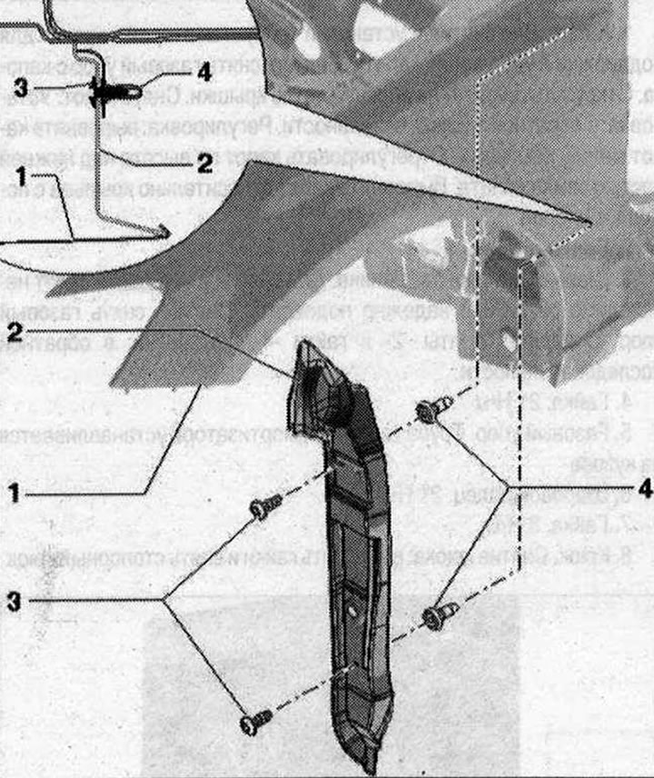

Removing the wing trim

  • 1. Wing
  • 2. End trim of the wing. Remove the front wheel. Remove the rear part of the mudguard. Disconnect the washer reservoir on the left side. Unscrew the bolts "3", unlock in the rear bracket of the wing and remove the end part in a downward direction
  • 3. Bolts. 1.5 Nm
  • 4. Clamp 2x


[The full version is posted on the resource: AUDImanual.ru]
The article was checked by auto expert Timur Bazhenov
This article is available at russian, bulgarian, belarusian, ukrainian, serbian, croatian, romanian, polish, slovak, hungarian

Share information:
Previous articles
Audi Q Q5 Type 8R: Exterior
Next articles

Additional amplifiers
Radiator frame mounting diagram with attachments
Radiator frame, service position
Removal the hood
Removal the bonnet gas strut
Removal the bonnet seal
Scheme of installation of cable with hood lock shell


Similar articles on other Audi car models:
Electrical connection diagram for ignition switch, side light… Audi 80 B3 (1986-1991, petrol)
Front wing Audi 100 C4 (1990-1994)
Removal and installation the wing Audi A3 Type 8L (1996-2003)
Removal and installation the rear wing liner Audi A4 B6 (2000-2006)
Front wing Audi A6 C5 (1997-2004)
Front wing Audi A8 D2 (1994-2002)
Cooling system hose connection diagram Audi A2 (1999-2005)
Link to this page in different formats


Visitor comments

No comments yet


How much will 19 + 49 =


Q7 4L(2005-2015, diesel) 
  • General information
  • Operating instructions
  • Maintenance
  • Power unit
  • Diesels 3.0 l (BUG, BUN, CAS)
  • Diesels 3.0 l (CATA, CCMA)
  • Diesels 3.0 l (CJGA/CJGC)
  • Diesels 4.2 l (BTR, CCFA/CCFC)
  • Cooling system
  • Fuel and exhaust system
  • Engine management system
  • Starting and charging
  • Transmission
  • Automatic gearbox
  • Drive shafts
  • Chassis
  • Brake system
  • Front suspension
  • Rear suspension
  • Steering system
  • Body
  • Air conditioner
  • Exterior
  • Interior
  • Electrical equipment
  • Equipment and devices
  • Electrical circuits
 
Q5 8R(2008-2017) 
  • General information
  • User manual
  • Power unit
  • Petrol engine 2.0 l
  • Petrol engine 3.2 l
  • Fuel system (petrol)
  • Diesel 2.0 liter (CA)
  • Diesel 2.0 liter (CG/CJ/CM)
  • Diesel engine 3.0 l
  • Fuel system (diesel)
  • Transmission
  • Manual gearbox 0B1
  • Manual gearbox 0B2
  • Automatic gearbox 0B5
  • Automatic gearbox 0B6
  • Chassis
  • Front suspension
  • Rear suspension
  • Brake system
  • Steering
  • Body
  • Exterior
  • Interior
  • Doors, locks and windows
  • Safety system
  • Ventilation and heating
  • Electrical equipment
  • Power devices
  • Equipment and devices
  • Lighting and alarm
  • Audio system
  • Electrical circuits
 
AudiManual.ru © 2017-2026 · Mobile version · Feedback · Sitemap: EN BG BY UA RS HR RO PL SK HU · Site search · News and articles
80 B2 · 80 B3 petrol · 80 B3 · 80 B4 · 100 C3 diesel · 100 C3 petrol · 100 C3 · 100 C4 petrol · 100 C4 · A3 Type 8L · A4 B5 petrol · A4 B5 · A4 B6 petrol · A4 B6 · A4 B7 · A4 B8 · A6 C4 · A6 C5 · A6 C5 Allroad · A8 D2 · Q5 Type 8R · Q7 Typ 4L · Audi A2 ·
This site uses cookies 🍪. Click the button to accept this fact.