Repair Chevrolet Repair Toyota Repair Honda Repair AvtoVAZ Repair Mercedes-Benz Repair BMW Repair Opel
Home  |  Contacts  |  Sitemap  |    
English Русский
Български
Беларускі
Український
Српски
Hrvatski
Română
Polski
Slovenský
Magyar
AudiManual.ru


  • AUDI 80
  • AUDI 100
  • AUDI A3
  • AUDI A4
  • AUDI A6
  • AUDI A8
  • AUDI Q
  • OTHER
  • ARTICLES
Q7 Typ 4L (2005-2015, diesel) Q5 Type 8R (2008-2017)

Radiator frame mounting diagram with attachments (Audi Q5-8R)

  • Home
  • Audi Q
  • Q5 Type 8R (2008-2017)
  • Body
  • Exterior
  • Radiator frame mounting diagram with attachments
            0
Table of contents: Remove the radiator frame trim ↓ Radiator frame stretcher ↓ Removal the casing of the water… ↓
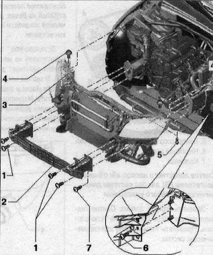
Radiator frame mounting diagram with attachments 1. Bolt. 55 N·m. 3 pcs. on each side; 2. Safety…

Radiator frame mounting diagram with attachments 1. Bolt. 55 N·m. 3 pcs. on each side; 2. Safety bar. Fixed with bolt "7" on the radiator frame. When dismantling the radiator frame, it is not necessary to remove it from the brackets; 3. Radiator frame. Before removing, drain the radiator coolant. Removal: remove the radiator frame trim. Remove the front bumper. Disconnect all electrical wires and hoses going to the radiator frame from the connection points. Disconnect the hood lock cable on the coupling. Unscrew bolts "5". Unscrew bolts "1" from the side member (3 pcs on each side). The safety bars with brackets are each fixed with one bolt "1" on the radiator frame and should not be removed. Unscrew the bolts "6" from below on the radiator frame. Remove the radiator frame with the headlights in the forward direction. Installation: in the reverse order. After installation, it is necessary to adjust the headlights; 4. Bolt. 5 Nm; 5. Bolt. 1-.5 Nm; 6. Bolt. 4 Nm. Serves to secure the safety bar to the radiator frame


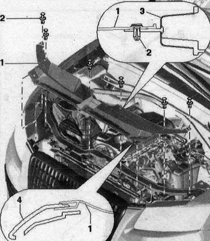
Remove the radiator frame trim


  • 1. Trim. To remove, unscrew the locking pin, which will unlock the clamp. Remove the clamp from the trim. Remove the trim from the radiator grille in the rear direction. When installing, the projections of the trim must be fixed in the radiator grille and on the side of the bumper trim. Install the clamp through the trim into the radiator frame and press in the locking pin
  • 2. Expansion piston. 4x. When removing, unscrew the clamping pin. When installing, press in the clamping pin
  • 3. Radiator frame
  • 4. Radiator grille

4. Radiator grille


Radiator frame stretcher
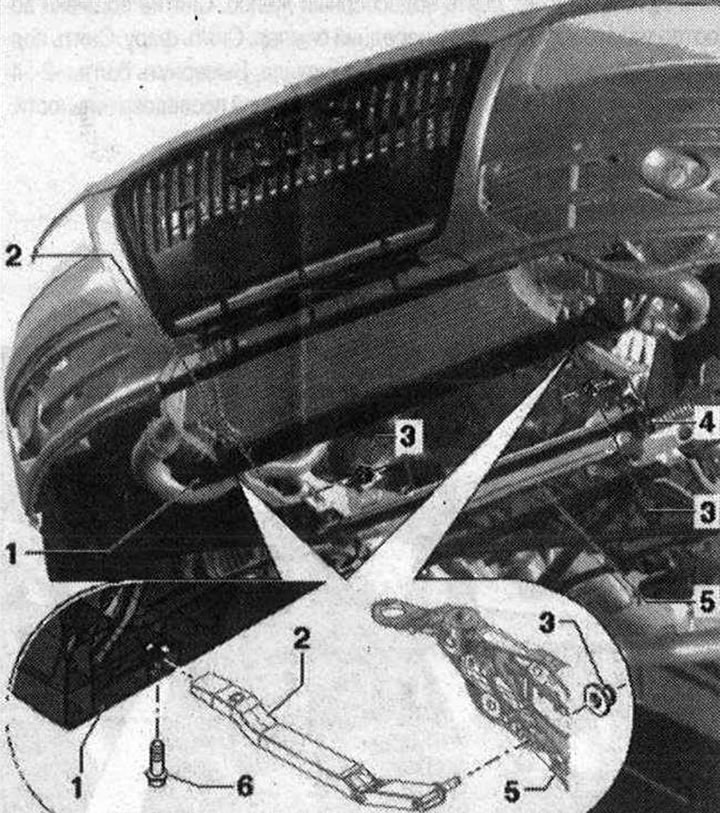


Radiator frame stretcher

  • 1. Radiator frame
  • 2. Right stretcher for radiator frame. Fastened with nut "6" on the radiator frame
  • 3. Nut. 23 Nm
  • 4. Radiator frame brace, left. Fastened with nut "6" to the radiator frame
  • 5. Subframe
  • 6. Bolt. 5 Nm
  • 7. Bracket. Insert from below into the radiator frame


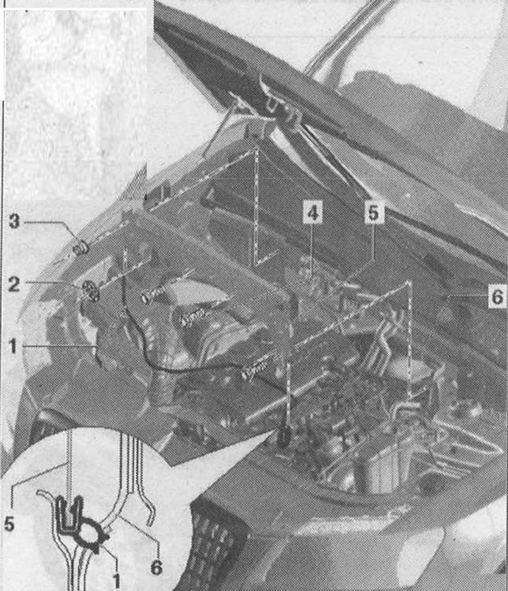
Removal the casing of the water drainage box
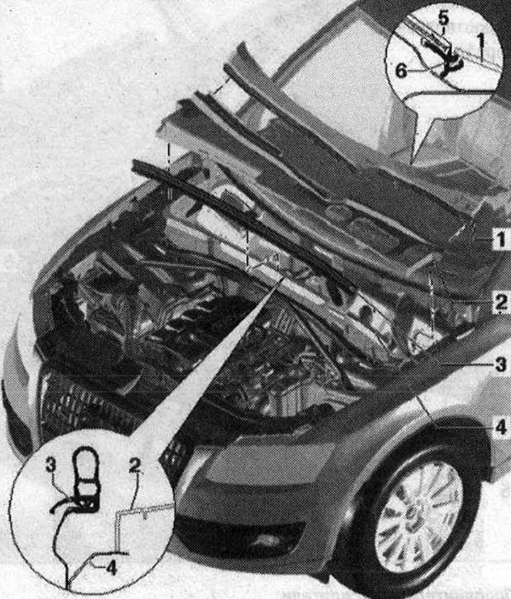


Removal the casing of the water drainage box

  • 1. Deflector. Windscreen wiper arm removed. Additional trims (left, center and right) removed. Disconnect clamps "3". To facilitate removal/installation, spray a small amount of industrial soap solution onto the windshield mounting frame. Remove the deflector, starting from the edge of the glass, from the edging frame vertically upwards. Risk of breaking the glass during installation. Do not knock the deflector during installation. Carefully press the fairing, starting from the side, into the mounting frame
  • 2. Water box cover. When removing, disconnect only the front clamp. Lift the cover from the front and remove it from the water box casing
  • 3. Gasket. Remove from the body flange from the side towards the rear.
  • 4. Front wall of the water drainage box
  • 5. Windshield
  • 6. Edging

Installation diagram of the front wall of the water drainage box 1. Gasket. Slide the gasket from…

Installation diagram of the front wall of the water drainage box 1. Gasket. Slide the gasket from below; 2. Clamping washer. When installing, press on the threaded pin of the front wall of the water drainage box; 3. Nut. 4 Nm; 4. Bolt 7 Nm; 5. Front wall of the water drainage box. To remove, unscrew the bolts "4" and nut "3". Installation is carried out in the reverse order; 6. Drainage box


(The original text of the material can be found on the website AUDImanual.ru)
The article was checked by auto expert Timur Bazhenov
This article is available at russian, bulgarian, belarusian, ukrainian, serbian, croatian, romanian, polish, slovak, hungarian

Share information:
Previous articles
Audi Q Q5 Type 8R: Exterior
Next articles

Radiator frame, service position
Additional amplifiers
Wing assembly diagram
Removal the hood
Removal the bonnet gas strut


Similar articles on other Audi car models:
Radiator Fan Wiring Diagram Audi 80 B3 (1986-1991, petrol)
Radiator — removal, inspection, cleaning and installation Audi 100 C3 (1982-1990, diesel)
Removal and installation the radiator and fan Audi A3 Type 8L (1996-2003)
Front part of the body — radiator frame with attachments Audi A4 B8 (2007-2015)
Diagram 1-12. Radiator fan thermal relay Audi A6 C5 Allroad (1999-2005)
Radiator check Audi A8 D2 (1994-2002)
Removal and installation the radiator frame with attachments Audi A2 (1999-2005)
Link to this page in different formats


Visitor comments

No comments yet


How much will 37 + 49 =


Q7 4L(2005-2015, diesel) 
  • General information
  • Operating instructions
  • Maintenance
  • Power unit
  • Diesels 3.0 l (BUG, BUN, CAS)
  • Diesels 3.0 l (CATA, CCMA)
  • Diesels 3.0 l (CJGA/CJGC)
  • Diesels 4.2 l (BTR, CCFA/CCFC)
  • Cooling system
  • Fuel and exhaust system
  • Engine management system
  • Starting and charging
  • Transmission
  • Automatic gearbox
  • Drive shafts
  • Chassis
  • Brake system
  • Front suspension
  • Rear suspension
  • Steering system
  • Body
  • Air conditioner
  • Exterior
  • Interior
  • Electrical equipment
  • Equipment and devices
  • Electrical circuits
 
Q5 8R(2008-2017) 
  • General information
  • User manual
  • Power unit
  • Petrol engine 2.0 l
  • Petrol engine 3.2 l
  • Fuel system (petrol)
  • Diesel 2.0 liter (CA)
  • Diesel 2.0 liter (CG/CJ/CM)
  • Diesel engine 3.0 l
  • Fuel system (diesel)
  • Transmission
  • Manual gearbox 0B1
  • Manual gearbox 0B2
  • Automatic gearbox 0B5
  • Automatic gearbox 0B6
  • Chassis
  • Front suspension
  • Rear suspension
  • Brake system
  • Steering
  • Body
  • Exterior
  • Interior
  • Doors, locks and windows
  • Safety system
  • Ventilation and heating
  • Electrical equipment
  • Power devices
  • Equipment and devices
  • Lighting and alarm
  • Audio system
  • Electrical circuits
 
AudiManual.ru © 2017-2026 · Mobile version · Feedback · Sitemap: EN BG BY UA RS HR RO PL SK HU · Site search · News and articles
80 B2 · 80 B3 petrol · 80 B3 · 80 B4 · 100 C3 diesel · 100 C3 petrol · 100 C3 · 100 C4 petrol · 100 C4 · A3 Type 8L · A4 B5 petrol · A4 B5 · A4 B6 petrol · A4 B6 · A4 B7 · A4 B8 · A6 C4 · A6 C5 · A6 C5 Allroad · A8 D2 · Q5 Type 8R · Q7 Typ 4L · Audi A2 ·
This site uses cookies 🍪. Click the button to accept this fact.