



The clutch consists of a pressure plate with a friction surface, a driven plate with friction linings, and a second friction surface, which is the flywheel. The flywheel and pressure plate are directly connected to the engine crankshaft, and the driven plate is mounted on the splines of the drive shaft of the gearbox.
The diaphragm spring mechanism creates a force that combines the work of the flywheel, pressure plate and slave disk to ensure joint rotation, in which case the clutch is engaged and transmits torque from the engine to the gearbox. The clutch is controlled by the clutch pedal.
The clutch is released as follows. Pressing the clutch pedal moves the piston in the master cylinder, compressing the fluid, the pressure of which is transmitted through the hose to the slave cylinder of the clutch, the piston of which in turn acts on the clutch release fork. The clutch release fork moves the clutch release bearing, which presses on the center of the diaphragm spring, thus releasing the engagement force along the perimeter of the spring and moves the pressure plate back. This releases the slave disk, after which the engine shaft and gearbox shaft can rotate independently of each other.
Friction linings are riveted to both sides of the driven disk. The leading part of the disk is connected to the hub through parts of the torsional vibration damper, which provides an elastic connection between them. The vibration damper reduces dynamic loads that cause twisting (unwinding) transmission shafts, which occur when the vehicle's speed changes abruptly, when driving over uneven roads, when the clutch is engaged abruptly, and also due to uneven engine torque. Elastic vibrations of transmission parts lead to noise in mechanisms and units, as well as vibrations, which may result in damage to parts if the amplitude of elastic vibrations reaches significant values. A damper is used to absorb the energy of elastic torsional vibrations.
The clutch adjustment occurs automatically.
Depending on the design of the flywheel, different clutch discs are used. When installing a one-piece flywheel on the engine, a clutch disc with vibration damper springs is installed. When installing a two-section (double mass) flywheel with an intermediate elastic element, with a damping system, a clutch disc is installed without vibration damper springs.
Each time the clutch is engaged/disengaged, there is minor wear of the friction linings of the clutch drive disc. As a result of wear, the drive disc must be replaced after the vehicle has traveled 100,000 km. The distance traveled depends on the loads on the vehicle during operation and driving style.
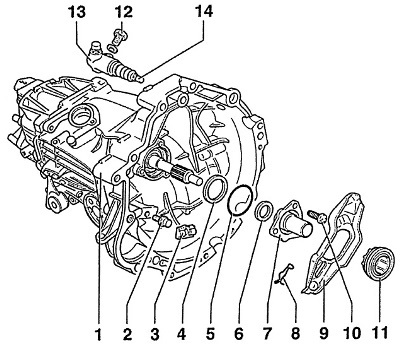
Fig. 5.1. Clutch
1 - manual gearbox,
2 - support with a spherical tip,
The spherical tip must be lubricated with molybdenum disulfide (MoS₂) lubricant.
Tightening torques:
- to the gearbox housing made of aluminum alloy 25 Nm;
- to the gearbox housing made of magnesium alloy 20 Nm.
3 - intermediate element,
4 - disc spring,
The convex side of the spring should face the guide bushing.
5 - round sealing ring,
A new sealing ring must be used during installation.
6 - gearbox input shaft sealing ring,
Install until it stops.
7 - clutch release bearing guide sleeve,
8 - spring,
Mounted on the clutch release fork,
9 - clutch release fork,
10 - self-locking bolt,
Tightening torques:
- to the gearbox housing made of aluminum alloy 35 Nm.
- to the gearbox housing made of magnesium alloy 25 Nm.
11 - clutch release bearing,
The bearing must not be washed in a solvent, otherwise the lubricant will be washed out of it. A bearing that operates noisily must be replaced,
12 - bolt, 20Nm,
13 - clutch slave cylinder,
14 - pusher,
Apply copper-based grease to the pushrod head.
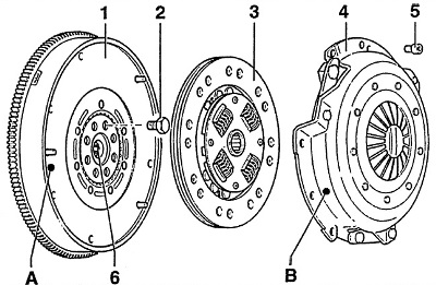
Fig. 5.2. Flywheel and clutch disc
1 - flywheel,
2 - bolt, 60 Nm + + tighten by 90°
On models with a V6 diesel engine - 60 Nm + turn further by 180°.
New bolts must be used during installation.
3 - leading clutch disc,
Mounting position: The springs must be located on the pressure plate side.
4 - pressure plate,
5 - bolt, 25 Nm,
6 - needle bearing,
A, B - color marks (only on models with 2.5/2.8-I engines)
When installing the pressure plate, it is necessary to align the marks on the flywheel and pressure plate.
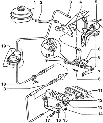
Fig. 5.3. Hydraulic clutch drive
1 - brake system replenishment tank,
2 - hose,
3 - clutch pipeline,
4 - bracket,
5 - clutch pedal,
6 - bolt, 20 Nm,
7 - finger,
8 - clutch master cylinder,
9 - sealing ring,
10 - safety clamp,
11 - gearbox,
12 - clutch slave cylinder,
After removing the clutch slave cylinder, do not press the clutch pedal. If the clutch slave cylinder has a plastic support ring, lubricate the end surface of the ring before installation. When installing the clutch slave cylinder, press the piston into the cylinder so that the mounting bolt can be screwed in.
13 - bleed nipple, 5 Nm,
When bleeding the clutch hydraulic system, do not allow brake fluid to come into contact with the gearbox.
14 - dust cap,
15 - dust cover,
16 - gearbox bracket,
17 - Allen bolt, 25 Nm,
18 - nut, 2 Nm,
19 - seal