



Table of contents: Front-wheel drive cars AUDI A6 ↓ All-wheel drive cars AUDI AB quattro ↓
Front-wheel drive cars AUDI A6
The rear suspension is made using longitudinal levers connected to a beam fixed to the body. A stabilizer is installed in front of the rear beam, which reduces the roll of the car on turns. The rear beam is attached to the body through rubber-metal bushings. Two shock absorbers and two springs are used to cushion the rear beam. As a result of the separate location of the springs and shock absorbers of the rear suspension, the volume of the luggage compartment has increased.
This chapter mainly describes the rear suspension of front-wheel drive vehicles.
All-wheel drive cars AUDI AB quattro
The rear suspension is made with transverse double levers and consists of a beam, two transverse levers and one shock absorber strut on each side of the car. The beam is attached to the body through four rubber-metal bushings. The transmission of motion to the wheels and the damping of motion transmitted to the shock absorber struts is carried out through the upper and lower levers.
Attention. Welding and straightening works are not allowed on the load-bearing elements of the rear suspension. When installing, it is necessary to use new self-locking nuts and replace bolts that have traces of corrosion.
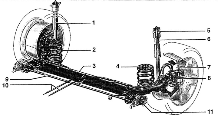
Fig. 8.1. Rear suspension of front-wheel drive vehicles
1 - shock absorber,
2 - spring,
3 - beam,
4 - upper spring support,
5 - shock absorber support,
6 - stop buffer,
7 - brake disc,
8 - hub bearing,
9 - stabilizer,
10 - handbrake cables,
11 - rubber-metal support.
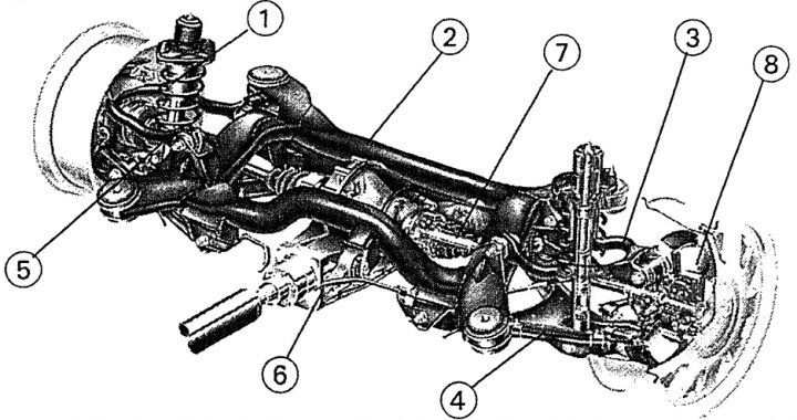
Fig. 8.2. Rear suspension of all-wheel drive vehicles (quattro)
1 - shock absorber strut,
2 - additional beam,
3 - upper transverse arm,
4 - lower transverse arm,
5 - rubber-metal support,
6 - differential,
7 - drive shaft,
8 - brake disc
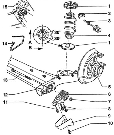
Fig. 8.3. Elements of the rear suspension of front-wheel drive vehicles
1 - upper spring support,
2 - wheel speed sensor holder,
3 - wheel speed sensor,
4 - coil spring,
The spring must not have any damage to the varnish coating.
5 - hub bearing,
6 - rubber-metal support with bracket,
Before installation, clean the support surfaces of the bracket with the rubber-metal support. After installation, check and, if necessary, adjust the track of the rear wheels.
7 - nut,
It is recommended to use a new nut during installation.
8-bolt M12x1. 5x90. 110 Nm + turn to an angle of 90°,
It is recommended to use a new bolt during installation.
9 - protective cover,
10 - bolt, 10 Nm,
11 - bolt M12x1.5x60, 110 Nm + tighten by 90°,
It is recommended to use a new bolt during installation.
12 - rear beam,
Before installation, clean the rear beam support surfaces.
13 - bolt M14x1.5x190, 120 Nm + tighten by 90°,
It is recommended to use a new bolt during installation.
14 - stabilizer lock,
15 - threaded hole.
A - direction of vehicle movement, B - right side of the vehicle.
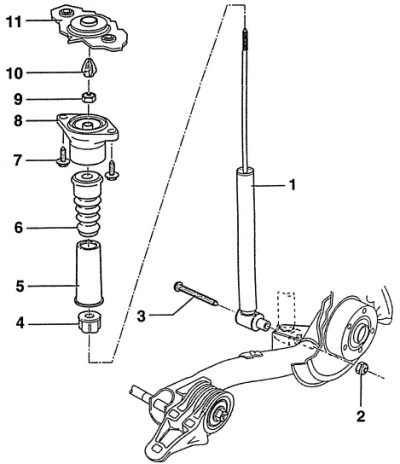
Fig. 8.4. Shock absorber of front-wheel drive vehicles
1 - gas-filled shock absorber,
The shock absorber is replaced as an assembly.
2 - nut,
It is recommended to use a new nut during installation.
3 - bolt, 50 Nm + tighten by 90°,
When installing, you must use a new bolt. Tighten the bolt after installing the car on the wheels.
4 - protective cover,
5 - protective cover,
6 - buffer,
7 - bolt, 45 Nm,
8 - upper shock absorber mount,
9 - self-locking nut, 25 Nm,
When installing, you must use a new nut. When unscrewing the nut with a second key, hold the shock absorber rod from turning.
10 - mounting cap,
11 - threaded holes in the car body.