
Table of contents: General information and instructions… ↓ Installation diagram (until calendar… ↓ Installation diagram (from calendar… ↓ Design of the mobile connection kit.… ↓ Components for preparing for mobile… ↓ MMI mobile phone preparation… ↓ Mobile phone connection kit contents ↓ Microphone unit in the front ceiling… ↓
General information and instructions (until calendar week 44/08)
The telephone system can be presented in the following variants.
Preparing for mobile phone installation
The R36 telephone transceiver is connected to the MMI infotainment system via the CAN/MOST bus. Signals are also transmitted via the R152 Bluetooth antenna. A holder for the R126 telephone is installed in the center console. Control is via the control module. multimedia system "E380" (MOST), radio "R" (CAN) or mobile phone "R54". The microphones of the front microphone unit are built into the front "W1" light. roof module "R164". One of the microphones (microphone of phone "R38") is connected to the transceiver device of phone "R36".
Built-in phone with Bluetooth interface
A car phone with Bluetooth allows additional. use mobile phones that have this interface. Mobile phones with Bluetooth do not necessarily have to be connected to the cradle and the vehicle hands-free system. The connection is made exclusively via the wireless Bluetooth interface. It is also possible to read information from the mobile phone SIM card "R54" (phone book). The car phone with Bluetooth has its own wireless Bluetooth headset with a SIM card insert and a charging cup. The Bluetooth car phone and the R54 mobile phone can be controlled via the Bluetooth headset, the hands-free device on the multi-function steering wheel, and via the system. speech dialogue. The R36 telephone's transceiver is connected to the MMI Infotainment system via the MOST bus. The microphones of the front microphone unit are integrated into the W1 headlight. roof module "R164". One of the microphones (microphone of phone "R38") is connected to the transceiver device of phone "R36".
Mobile phone connection kit
Under the storage compartment in the center of the console there is a connection socket for the connection kit. The microphones of the front microphone unit are built into the front "W1" illumination lamp. roof module "R164". The microphone (phone microphone "R38") is connected via a connector. The connector has an antenna input for the radio antenna, telephone, and navigation system "R52" (antenna on the roof). Troubleshooting. carried out in the Guided Troubleshooting mode.
Bluetooth Technology Guidelines
Bluetooth technology uses a standardized radio connection to transmit data between the R36 phone's transceiver and the R37 handset/R54 mobile phone. The R36 phone's transceiver contains an additional. transceiver unit. The separate Bluetooth antenna "R152" connects the transceiver of the telephone "R36" and the telephone mount "R126"/mobile phone "R54", and thus the telephone handset "R37"/mobile phone "R54" can be controlled remotely, i.e. wirelessly. The radio communication range is about 10 meters.
Installation diagram (until calendar week 44/08)
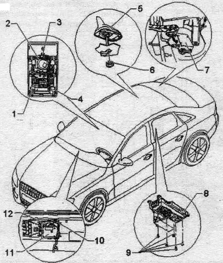
1. Front left microphone "R140".
2. Ceiling lamp in the lane. interior parts -W1-: microphone unit in front, roof module "R164".
3. Plug connector (T6c).
4. Front right microphone "R141".
5. Antenna for radio, telephone, navigation. syst. "R52".
6. Nut: 6 Nm.
7. Mob booster. phone "R86".
8. Phone holder "R126".
9. Bolt: 1 Nm.
10. Switching block.
11. Device for receiving and transmitting telephone signals "R36".
12. Antenna for Bluetooth "R152".
Installation diagram (from calendar week 45/08)
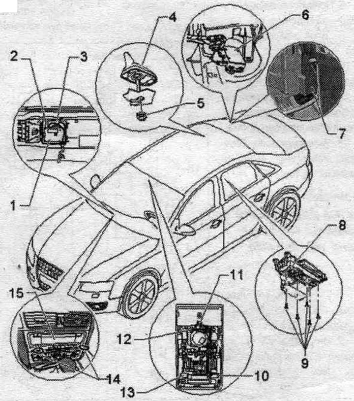
1. Device for receiving and transmitting telephone signals "R36".
2. Antenna for Bluetooth "R152".
3. Switching block.
4. Antenna for radio, telephone, navit, system. "R52".
5. Nut: 6 Nm.
6. Mob booster. phone "R86" (Sedan).
7. Mob booster. phone "R86" (Avant).
8. Phone holder "R126".
9. Bolt: 1 Nm.
10. Front right microphone "R141".
11. Ceiling lamp in the lane. interior parts "W1": microphone unit in front, roof module "R164".
12. Plug connector (T6c).
13. Front left microphone "R140".
14. Radio remover "T10057".
15. Used communications electronics 1 "J794".
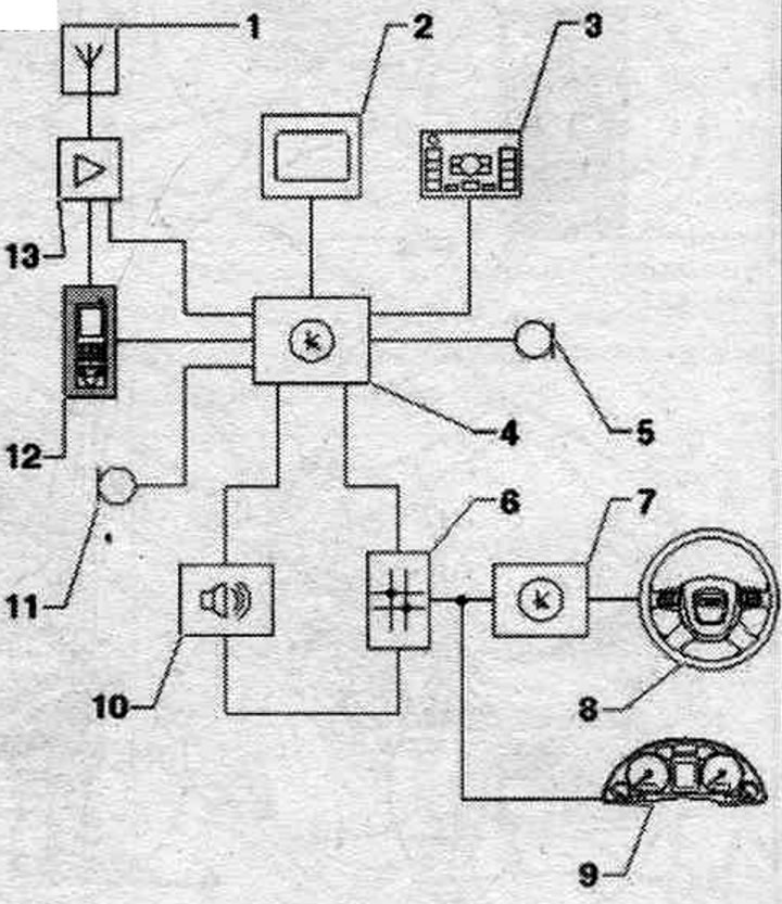
Design of the mobile connection kit. telephone (CAN)
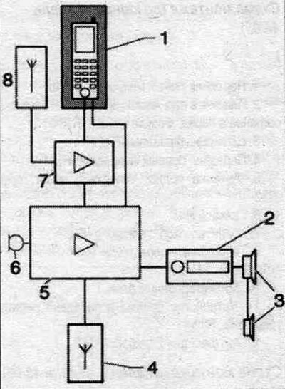
1. Phone holder "R126" with mobile phone "R54".
2. Radio "R" in the dashboard.
3. Acoustic systems.
4. Antenna system. Bluetooth "R152" on the phone's transceiver "R36".
5. Telephone transmitter and receiver "R36" under the front seat. passage.
6. Microphone block in lane. parts of the roof module "R164" in front, backlight lamp "W1".
7. Amplifier for mobile. phone "R86" behind the right side trim of the trunk.
8. Antenna for radio, telephone, navit, system. "R52" (antenna on the roof).
Components for preparing for mobile installation. mMI phone (until calendar week 44/08)
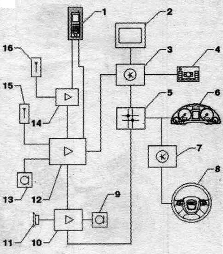
1. Phone holder "R126" with mobile phone "R54".
2. Indicator of used control body. and indication, front "J685" in the center of the lane. panels.
3. Used indicator and control module. information system "J523" in the front compartment on the left (MMI basic)/3a front panel (MMI).
4. Control module. multimedia system "E380" in the center, console.
5. Diagnostic interface of the data bus "J533" behind the front compartment on the left.
6. Used instrument cluster "J285" in the front panel.
7. Used steering column "J527" on the steering column switch module. columns.
8. Multifunctional steering wheel.
9. Microphone block in lane. parts of the roof module "R164" in front, backlight lamp "W1".
10. Used digital audio system "J525" behind the left side trim of the trunk.
11. Acoustic systems..
12. Telephone transmitter and receiver "R36" under the front seat. passage.
13. Microphone block in front, roof module "R164" (with telephone microphone "R38") in front, backlight lamp "W1".
14. Amplifier for mobile. phone "R86" behind the right side trim of the trunk.
15. Antenna system. Bluetooth "R152" on the phone's transceiver "R36".
16. Antenna for radio, telephone, navigation. syst. "R52" (antenna on the roof).
MMI mobile phone preparation components (from calendar week 45/08)
1. Antenna for radio, telephone, navigation. syst. "R52" (antenna on the roof).
2. Indicator of used control body. and indication, front "J685" in the center of the lane. panels.
3. Control module. multimedia system "E380" in the center, console.
4. Used information electronics 1 "J794" on the front panel.
5. Microphone block in the front, roof module "R164" (front right microphone "R141") in the front lighting lamp "W1".
6. Diagnostic interface of the data bus "J533" behind the front compartment on the left.
7. Used steering column "J527" on the steering column switch module. columns.
8. Multifunctional steering wheel.
9. Used instrument cluster "J285" in the front panel.
10. Used digital audio system "J525" behind the left side trim of the trunk.
11. Microphone block in the front, roof module "R164" (front left microphone "R140") in the front lighting lamp "W1".
12. Phone holder "R126" with mobile phone "R54".
13. Amplifier for mobile. phone "R86" behind the right side trim of the trunk.
Mobile phone connection kit contents
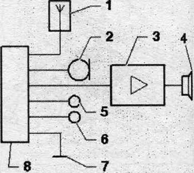
1. Antenna for radio, telephone, navigation. syst. "R52" (antenna on the roof).
2. Microphone block in lane. parts of the roof module "R164" in front, backlight lamp "W1".
3. Radio "R"/6/y digits, audio system "J525".
4. Acoustic systems.
5. Terminal 15.
6. Terminal 30.
7. Terminal 31.
8. Multi-pin connector, 18-pin (T18a) in the center, rear console.
Microphone unit in the front ceiling module "R164" (from calendar week 45/08)
The microphone (internal microphone "R74") is connected directly to the control unit. digital audio system "J525". Other microphones are connected to used communications electronics 1 "J794".
Microphone unit in the front roof module "R164"
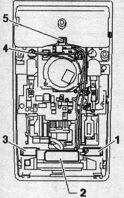
1. Microphone (blue) to the control unit. communications electronics 1 "J794".
2. Sending and receiving module 1 of space control. salon "G303".
3. Microphone (black) to the control unit. communications electronics 1 "J794".
4. Internal microphone "R74" (black) for used digital audio package "J525".
5. Multi-pin connector, 6-pin (T6c).
Connector pinout
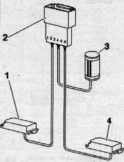
1. Front left microphone "R140" (black).
2. 6-pin connector (T6c), contacts 1-2: front left microphone "R140" (black), contacts 3-4: internal microphone "R74" (black), contacts 5-6: front right microphone "R141" (blue).
3. Internal microphone "R74" (black).
4. Front right microphone "R141" (blue).