
Repair Chevrolet Repair Toyota Repair Honda Repair AvtoVAZ Repair Mercedes-Benz Repair BMW Repair Opel
Home  |  Contacts  |  Sitemap  |    
English Русский
Български
Беларускі
Український
Српски
Hrvatski
Română
Polski
Slovenský
Magyar
AudiManual.ru


  • AUDI 80
  • AUDI 100
  • AUDI A3
  • AUDI A4
  • AUDI A6
  • AUDI A8
  • AUDI Q
  • OTHER
  • ARTICLES
B4 (1991-1996) B3 (1986-1991) B3 (1986-1991, petrol) B2 (1979-1986)

Automatic engine stop and start device «Stop-Start» circuit diagram (Audi 80 B2)

  • Home
  • Audi 80
  • B2 (1979-1986)
  • Electrical equipment
  • Electrical circuits
  • Automatic engine stop and start device «Stop-Start» circuit diagram
            0
Wiring diagram for the automatic engine stop and start device "Stop-Start".

For vehicles with chassis number up to 81ZBA 065 315
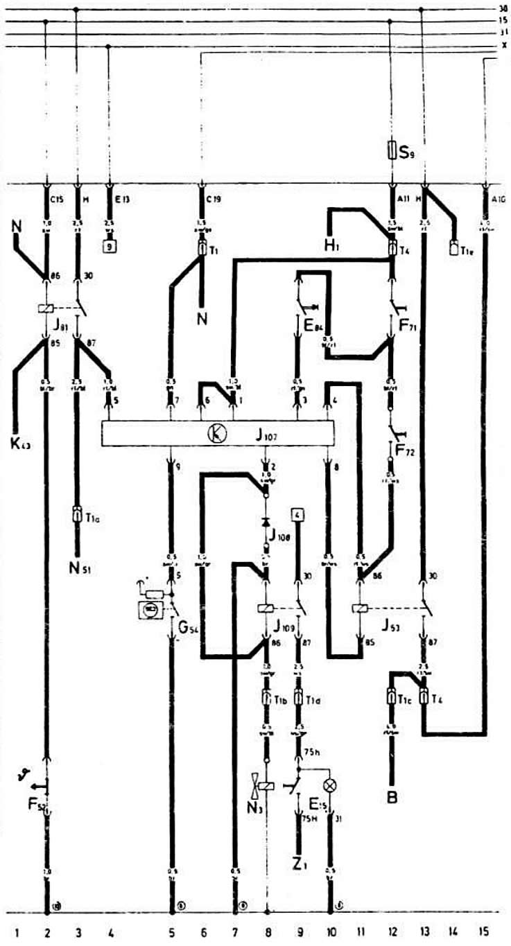


For vehicles with chassis number up to 81ZBA 065 315

On vehicles starting with chassis number 81ZBA 065 316
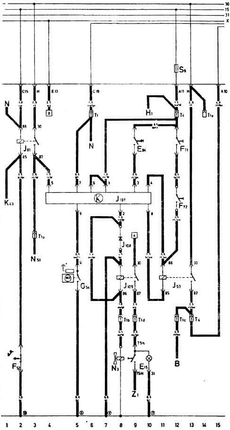


On vehicles starting with chassis number 81ZBA 065 316


Designation on the diagramNamePosition on the diagram
INTo the starter12
E15Rear Window Defogger Switch9, 10
E84Engine stop and start device switch9
F52Low Coolant Temperature Warning Light Sensor2
F71Clutch release sensor of the automatic engine stop and start device12
F72Automatic engine stop/start device accelerator pedal position sensor12
054Automatic engine stop and start device speed sensor5
H1To the sound signal10
J53Starter relay11-13
J81Intake manifold heating relay2,3
J107Automatic engine stop and start device control unit4-10
J108Automatic engine stop and start device cut-off diode8
J109Additional relay for switching on the rear window heating8,9
K43To the low coolant temperature warning light1
NIgnition coil
to terminal "15" of the ignition coil1
to terminal "1" of the ignition coil6
N51To the heating resistor of the intake manifold3
S9Fuse in the fuse box of the mounting block
T1Single plug connector (behind the instrument cluster)
T1aSingle plug connector (behind the instrument cluster)
T1bSingle plug connector (behind the instrument cluster)
T1sSingle plug connector (behind the instrument cluster)
T1dSingle plug connector (behind the instrument cluster)
T1eSingle plug connector (behind the instrument cluster)
T44-pin connector (behind the instrument cluster)
Z1To the rear window heating element9
(8)Ground connection point behind the instrument cluster
(10)Ground connection point in the engine compartment on the right
The article was checked by auto expert Georgy Rodionov
This article is available at russian, bulgarian, belarusian, ukrainian, serbian, croatian, romanian, polish, slovak, hungarian

Share information:
Previous articles
Audi 80 B2: Electrical circuits
Next articles

Wiring diagram for Audi «80 S», «80 LS», «80 GLS» 1981 model year
Wiring diagram for Audi «80 LS», «80 GLS» 1979 model year
Electrical diagram of cars Audi «80», «80 L» 1979 model year
Legend of the electrical equipment diagrams of the Audi «80» car…
Features of the electrical equipment diagram of the Audi «80 GLE»
Fog light wiring diagram since 1985 model year
Wiring diagram for Audi «80» 1985 model year
Features of the Audi «80» car diagram with EP engine since 1985…


Similar articles on other Audi car models:
First engine start after major overhaul Audi 100 C4 (1990-1994)
Ignition switch and engine start Audi A3 Type 8L (1996-2003)
Start-stop system, since May 2009 Audi A4 B7 (2004-2008)
Diagram 4-3. Battery, starter, generator, engine start interlock… Audi A6 C5 Allroad (1999-2005)
Automatic transmission Audi A8 D2 (1994-2002)
Start-stop mode key Audi Q5 Type 8R (2008-2017)
Towing to start the engine Audi A2 (1999-2005)
Link to this page in different formats


Visitor comments

No comments yet


How much will 10 + 42 =


80(B4, 1991-1996) 
  • General information
  • User manual
  • Maintenance
  • Troubleshooting
  • Power unit
  • Engine
  • Cooling system
  • Heating and ventilation
  • Petrol injection
  • Diesel fuel system
  • Fuel system
  • Exhaust systems
  • Ignition system
  • Transmission
  • Clutch
  • Car gearbox
  • Chassis
  • Brake system
  • Suspension and steering wheel
  • Body
  • Body and trim
  • Electrical equipment
  • Electrical system
  • Electrical circuits
 
80(B3, 1986-1991) 
  • General information
  • Repair characteristics
  • Maintenance
  • Power unit
  • Gasoline engine
  • Diesel engine
  • Engine lubrication system
  • Fuel system (gasoline)
  • Injection system (gasoline)
  • Fuel system (diesel)
  • Ignition system
  • Cooling system
  • Heater
  • Exhaust system
  • Transmission
  • Clutch and gearbox
  • Chassis
  • Steering
  • Brake system
  • Car suspension
  • Body
  • Body elements
  • Electrical equipment
  • Power devices
  • Lighting and appliances
  • Electrical circuits
 
80(B3, 1986-1991, petrol) 
  • General information
  • User manual
  • Maintenance
  • Power unit
  • Engine 4-cylinder
  • Engine 5-cylinder
  • Cooling system
  • Fuel and exhaust systems
  • Ignition system
  • Transmission
  • Clutch
  • Mechanical transmission
  • Automatic transmission
  • Drive shafts
  • Chassis
  • Brake system
  • Suspension
  • Steering
  • Body
  • Exterior
  • Interior
  • Electrical equipment
  • Equipment and devices
  • Electrical circuits
 
80(B2, 1979-1986) 
  • General information
  • User manual
  • Power unit
  • Engine FZ
  • Engine EP, YP, YZ, DT, DS, DZ
  • Transmission
  • Clutch
  • 4 speed gearbox
  • 5 speed gearbox
  • Front wheel drive
  • Chassis
  • Front suspension
  • Rear suspension
  • Steering
  • Brake system
  • Electrical equipment
  • Equipment and devices
  • Electrical circuits
 
AudiManual.ru © 2017-2026 · Mobile version · Feedback · Sitemap: EN BG BY UA RS HR RO PL SK HU · Site search · News and articles
80 B2 · 80 B3 petrol · 80 B3 · 80 B4 · 100 C3 diesel · 100 C3 petrol · 100 C3 · 100 C4 petrol · 100 C4 · A3 Type 8L · A4 B5 petrol · A4 B5 · A4 B6 petrol · A4 B6 · A4 B7 · A4 B8 · A6 C4 · A6 C5 · A6 C5 Allroad · A8 D2 · Q5 Type 8R · Q7 Typ 4L · Audi A2 ·
This site uses cookies 🍪. Click the button to accept this fact.