
Repair Chevrolet Repair Toyota Repair Honda Repair AvtoVAZ Repair Mercedes-Benz Repair BMW Repair Opel
Home  |  Contacts  |  Sitemap  |    
English Русский
Български
Беларускі
Український
Српски
Hrvatski
Română
Polski
Slovenský
Magyar
AudiManual.ru


  • AUDI 80
  • AUDI 100
  • AUDI A3
  • AUDI A4
  • AUDI A6
  • AUDI A8
  • AUDI Q
  • OTHER
  • ARTICLES
C5 Allroad (1999-2005) C5 (1997-2004) C4 (1994-1997)

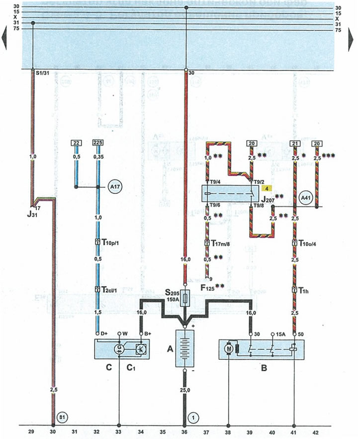
Diagram 4-3. Battery, starter, generator, engine start interlock relay (Audi A6 C5)
  • Home
  • Audi A6
  • C5 Allroad (1999-2005)
  • Electrical equipment
  • Electrical circuits
  • Diagram 4-3. Battery, starter, generator, engine start interlock relay
            0

Diagram 4-3. Battery, starter, generator, engine start interlock relay


Diagram 4-3. Battery, starter, generator, engine start interlock relay


Abattery
INstarter
WITHgenerator
C1voltage regulator
F125steering column switch
J31interval mode relay for windshield washer and wiper
J207engine start interlock relay
S205fuse 2 x 30A
Tlhblack plug on the right side of the engine compartment
T2cl2-pin black plug, in the engine compartment on the right side
T99-pin brown plug engine starter immobilizer relay
T10o10-pin brown connector for under cowl fuse/relay box
T10p10-pin black plug for under cowl fuse/relay box
T17m17-pin blue plug on the front pillar on the right
()connection to ground (-) battery - body
81ground (-) 1 in the instrument cluster wiring harness
A17terminal 61 wire in the instrument panel wiring harness
A41positive potential wire terminal 50 in the wiring harness on the instrument panel
*cars with manual transmission
**cars with automatic transmission 01V/01L
***cars with automatic transmission Multitronic 01J
The article was checked by auto expert Alexey Ivanov
This article is available at russian, bulgarian, belarusian, ukrainian, serbian, croatian, romanian, polish, slovak, hungarian

Share information:
Previous articles
Audi A6 C5 Allroad: Electrical circuits
Next articles

Schematic 4-2. Ignition switch, unloader relay terminal X,…
Diagram 4-1. Points of «mass» (-)
Diagram 4-4. Light switch, left steering column switch...
Scheme 4-5. Instrument lighting regulator, headlight optical…
Diagram 4-6. Hazard warning light switch
Scheme 4-7. Glass cleaner and washer


Similar articles on other Audi car models:
Electrical connection diagram of the battery, starter and… Audi 80 B3 (1986-1991, petrol)
Battery, starter, generator (diesel engine) Audi 100 C3 (1982-1990)
Battery, starter, generator, fuse box... Audi A3 Type 8L (1996-2003)
Battery, starter, alternator Audi A4 B5 (1994-2001, petrol)
Starting the engine Audi A8 D2 (1994-2002)
2.0L petrol engine (CDNB, CDNC, SAEV, CADA): battery, power… Audi Q5 Type 8R (2008-2017)
Towing to start the engine Audi A2 (1999-2005)
Link to this page in different formats


Visitor comments

No comments yet


How much will 12 + 25 =


A6(C5 AR, 1999-2005) 
  • General information
  • User manual
  • Maintenance
  • Troubleshooting
  • Power unit
  • V6 petrol engines
  • V8 petrol engines
  • Diesel engines
  • Cooling and heating system
  • Injection system (gasoline)
  • Fuel system (diesel)
  • Supply system
  • Exhaust system
  • Ignition system
  • Transmission
  • Clutch
  • Mechanical gearbox
  • Automatic gearbox
  • Chassis
  • Brake system
  • Car suspension
  • Steering
  • Body
  • Body elements
  • Doors, locks and windows
  • Electrical equipment
  • Equipment and devices
  • Power devices
  • Electrical circuits
  • Schemes (petrol engine 2.7 l)
  • Schemes (petrol engine 4.2 l)
  • Schemes (diesel engine 2.5 l)
 
A6(C5, 1997-2004) 
  • General information
  • User manual
  • Maintenance
  • Power unit
  • Engine repair
  • Cooling system
  • Fuel system
  • Engine management
  • Fuel system (diesel)
  • Exhaust system
  • Transmission
  • Clutch
  • Car gearbox
  • Chassis
  • Front suspension
  • Rear suspension
  • Steering
  • Wheels and tires
  • Brake system
  • Body
  • Exterior
  • Interior
  • Electrical equipment
  • Air conditioner
  • Equipment and devices
  • Electrical circuits
 
A6(C4, 1994-1997) 
  • General information
  • User manual
  • Maintenance (gasoline)
  • Maintenance (Diesel)
  • Gasoline engines
  • 4 cylinder engines
  • 5 cylinder engines
  • 6 cylinder engines
  • Diesel engines
  • 4 cylinder engines
  • 5 cylinder engines
  • Engine repair
  • Removal and reassembly
  • Cooling system
  • Single point injection system
  • Multipoint injection system
  • MPI/MPFI injection system
  • Fuel system (diesel)
  • Exhaust system
  • Ignition system
  • Transmission
  • Clutch
  • Manual transmission
  • Automatic transmission
  • Drive shafts
  • Chassis
  • Brake system
  • Front suspension
  • Rear suspension
  • Steering
  • Body
  • Exterior (external elements)
  • Interior (internal elements)
  • Electrical equipment
  • Power devices
  • Lighting and appliances
  • Electrical circuits
 
AudiManual.ru © 2017-2026 · Mobile version · Feedback · Sitemap: EN BG BY UA RS HR RO PL SK HU · Site search · News and articles
80 B2 · 80 B3 petrol · 80 B3 · 80 B4 · 100 C3 diesel · 100 C3 petrol · 100 C3 · 100 C4 petrol · 100 C4 · A3 Type 8L · A4 B5 petrol · A4 B5 · A4 B6 petrol · A4 B6 · A4 B7 · A4 B8 · A6 C4 · A6 C5 · A6 C5 Allroad · A8 D2 · Q5 Type 8R · Q7 Typ 4L · Audi A2 ·
This site uses cookies 🍪. Click the button to accept this fact.