
Diagram 4-6. Hazard warning light switch
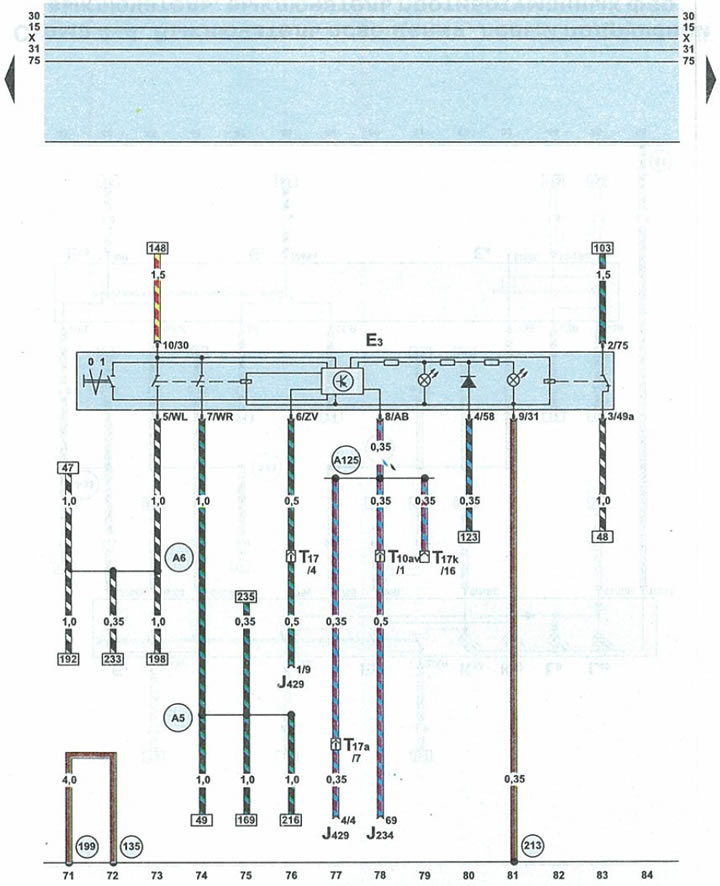
| EZ | hazard warning switch |
| J234 | airbag control unit |
| J429 | central locking control unit |
| T10av | 10-pin yellow plug on the front pillar on the right |
| T17 | 17-pin orange plug on the front pillar on the right |
| T17a | 17-pin brown plug on the front pillar on the right |
| T17k | 17-pin red connector on the fuse/relay box under the fairing |
| 135 | ground (-) 2 in instrument cluster wiring harness |
| 199 | ground (-) 3 in instrument cluster wiring harness |
| 213 | ground (-) 4 in instrument cluster wiring harness |
| A5 | positive potential wire (right turn signal) in the instrument panel wiring harness |
| A6 | positive potential wire (left turn signal) in the instrument panel wiring harness |
| A125 | collision signal transmission wire (crash signal) in the instrument panel wiring harness |