
Open large image in new window »
| Designation on the diagram | Position on the diagram | |
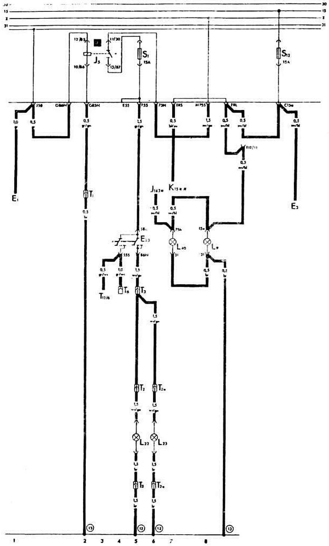
| E1 | Outdoor Light Switch | 1 |
| E3 | Hazard warning switch | 10 |
| E23 | Fog light and rear fog light switch | 4,5 |
| J5 | Fog light relay | 2,3 |
| J143 | Electronic control unit for idle speed control valve* | 6 |
| K15 | Carburetor air damper cover indicator lamp** | 7 |
| L9 | Outdoor Light Switch Lighting Lamp | 8 |
| L22 | Left fog light bulb | 5 |
| L23 | Right fog light bulb | 6 |
| L40 | Fog light and rear fog light switch illumination lamp | 7 |
| S1.S12 | Fuses on the mounting block | |
| T1 | Single plug connector (red and white, behind the instrument cluster) | |
| T2 | 2-Plug Connector (on the left in the powertrain compartment) | |
| T2a | 2-Plug Connector (on the right in the powertrain compartment) | |
| T3 | 3-pin connector (yellow, behind the instrument cluster) | |
| T6 | 6-pin connector (brown, behind the instrument cluster) | |
| T12 | 12-pin instrument cluster connector | |
| (12) | Ground connection point by soldering in the left front wire bundle | |
| (13) | Ground connection point by soldering in the instrument cluster wire harness | |
| [1] | Fog light relay |
* Only on vehicles with DZ engine
** Only for vehicles with EP engine
(The original article is located on the online resource: «AUDImanual»)