
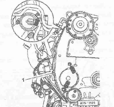
Unscrew the bolt "arrow up" for the rear cover "1" of the toothed belt.
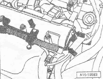
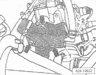
Unscrew the "arrow" bolts and put aside the bracket with electrical cables.
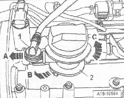
Remove the check valve "1" from the oil filler pipe "2" "arrow A" and put it aside. Unlock the lock "arrow B", turn the oil filler pipe counterclockwise "arrow C" and remove.
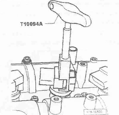
Install the "T10094 A" puller on all ignition coils - arrow, remove the ignition coils and simultaneously disconnect the electrical connectors of the ignition coils of cylinders 1...4.
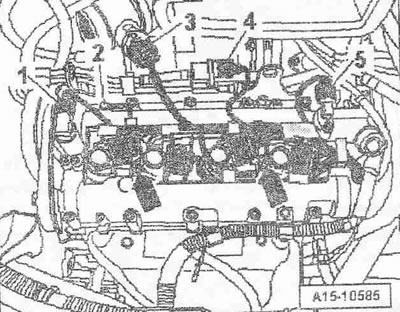
Disconnect the plug connectors:
1. Valve 1 for adjusting the valve timing "N₂05"
3. Air flow meter "G70"
4. Solenoid valve 1 of the container with activated carbon "N80"
5. Hall sensor "G40"
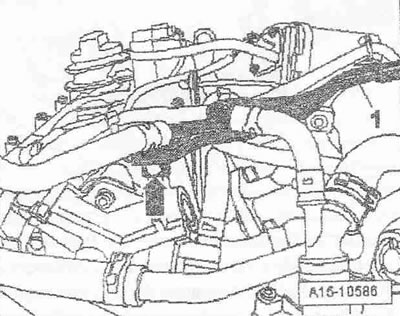
Unscrew bolt "2" for the ground wire and bolts "arrows" for the wiring, move the wiring with the wiring harness to the left. Unscrew bolt "arrow" and put aside coolant pipes "1".
 |
 |
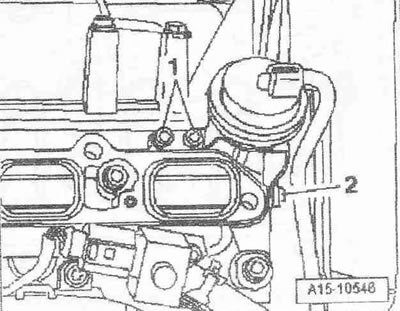
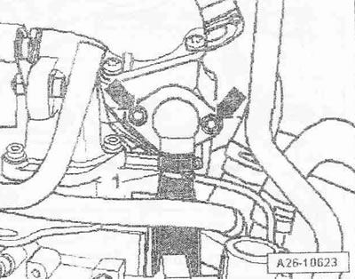
Unscrew the bolts "arrows" and put aside pipe "1" for the exhaust gas recirculation system.
Remove the fuel supply hose "2".
Caution! Before depressurizing the injection system, it is necessary to release the fuel pressure to residual pressure. When releasing residual pressure, place a clean rag around the connection point and carefully disconnect.
Unscrew threaded connections "1" and "3" and remove the high pressure line.
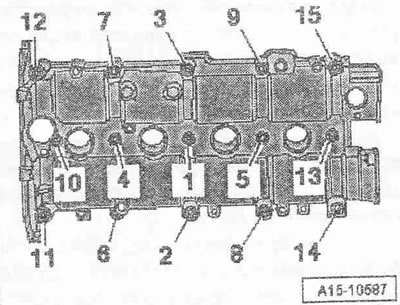
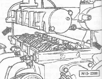
Loosen the camshaft housing bolts in the sequence "15... 1". Carefully lift the camshaft housing. Mark the alignment of the valve lever with roller and the hydraulic compensator for reassembly. Remove the valve lever with roller together with the hydraulic compensators and place on a clean lining.
Installation
Not a single piston at TDC.
Instructions. Replace the mesh oil filter in the cylinder head. Replace the bolts for the camshaft bearing housing. Risk of contamination of the lubrication system and bearings. Cover open engine parts.
Remove any remaining sealant from the cylinder head and camshaft housing. Clean the mounting surfaces; they should be free of oil and grease.
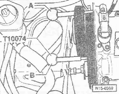
Check whether the camshafts are locked as follows: Locking pin "A" must be inserted through the locking hole of the intake camshaft gear into the calibration hole on the camshaft bearing housing. Locking pin "B" must be inserted through the locking hole of the exhaust camshaft gear into the calibration hole on the camshaft bearing housing.
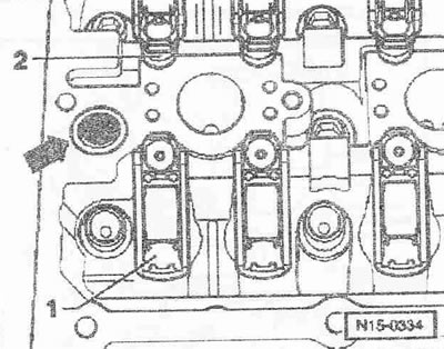
Check in each case whether the rocker arm fits correctly on the end of the valve stem "1" and whether it is clipped onto the hydraulic compensator "2". Insert a new mesh oil filter "arrow" into the cylinder head.
Caution! Risk of blocking lubrication system channels due to excess sealant. Sealant beads must not be thicker than the prescribed size.
Apply a thin, even layer of sealant to the areas marked with hatching in the figure on the clean sealing surface of the camshaft bearing housing.
To guide the camshaft bearing housing, screw 2 threaded pins M6x70 "arrows" into the cylinder head.
Caution! Risk of leaks from oil residues. When installing the camshaft housing, make sure that there is no oil on the mounting surfaces.
Carefully place the camshaft bearing housing vertically from above onto the grub screws and dowel pins in the cylinder head.
Instructions: Make sure that the camshaft housing is not warped.
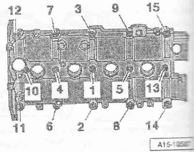
Tighten the camshaft housing bolts. After installing the camshaft housing, let the sealant dry for about 30 minutes. Install in reverse order, while it is necessary to install the high-pressure line. Install the pipe for the exhaust gas recirculation system. Install the rear cover for the toothed belt. Install the vacuum regulator of the intake manifold flap. Install the toothed belt of the mating drive.
Text provided by the online resource AUDIMANUAL