
Table of contents: A. Calculation of the maximum… ↓ B. Modification of valve seats ↓ Exhaust valve seat ↓
Instructions. If grinding does not achieve a perfect working surface of the valve seats, the seats must be machined. When repairing engines with leaky valves, it is not enough to machine or replace the cylinder seats and valves. Especially in engines with a long service life, it is necessary to check the valve guides for wear. Valve seats should only be machined until a perfect appearance of the working surface is achieved. Before reworking, it is necessary to calculate the maximum permissible rework size. If the machining tolerance is exceeded, the hydraulic control function may be impaired (clearance in the hydraulic compensator valve drive) will entail replacement of the cylinder head.
A. Calculation of the maximum allowable tolerance for rework
Insert the valve into the guide and press it tightly against the seat. If the valve is replaced during repair, a new valve should be used for measurements. Using the depth gauge "VAS 6082", measure the distance between the end of the valve stem (top edge) and the upper plane of the cylinder head. Calculate the maximum allowable rework allowance based on the measured distance and the minimum allowable dimension. Minimum dimension for intake and exhaust valves: 7.6 mm. Measured distance. Minimum dimension = maximum allowable rework allowance.
Example: measured distance 8.0 mm, minimum dimension 7.6 mm, maximum allowance for processing = 0.4 mm.
Instructions: If the maximum allowable machining allowance is 0 mm or less than 0 mm, repeat the measurement with a new valve. If the measurement result is always 0 mm or less than 0 mm, replace the cylinder head.
B. Modification of valve seats
Inlet valve seat:
- a. ∅ 28.7 mm,
- b. maximum allowance for finishing from 1.5...1.8 mm,
- z. Lower edge of the cylinder head,
- α. 45° valve seat chamfer angle,
- β. 30° angle of the upper correction chamfer,
- γ. 60° angle of the lower correction chamfer/
Exhaust valve seat
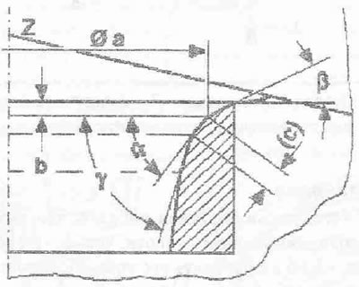
- a. ∅ 25.0 mm,
- b. maximum allowance for reworking, approx. 1.8 mm,
- z. lower edge of the cylinder head,
- α. 45° valve seat chamfer angle,
- β. 30° angle of the upper correction chamfer,
- γ. 60° angle of the lower correction chamfer.