



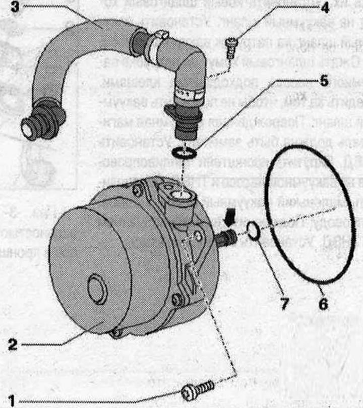
Vacuum pumps 1. Bolt 2x Torx 30.9 Nm. Unscrew to remove the pump. The pump cannot be further disassembled; 2. Vacuum pump; 3. Vacuum hose. Secure with hose clamps corresponding to the serial kit.; 4. Bolt. 5 Nm. The bolt installation depends on the model. Alternatively, secure the vacuum hose with a hose clamp that matches the serial kit.; 5-7. Sealing ring. Replace. Sealing ring installation depends on the model
Removal the vacuum pump of a 3.0 l TDI diesel engine
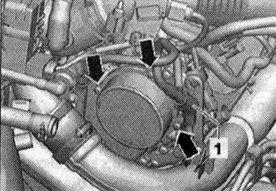
Replace the gaskets. The vacuum pump is installed on the right row of cylinders, back in the direction of travel "arrow".
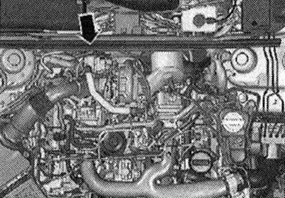
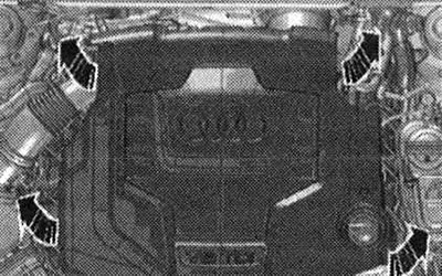
Carefully remove the engine cover from the mounting bolts one by one. Remove the right diagonal brace. Loosen the vacuum hose clamps.
Remove vacuum hose "1" from pump "3".
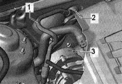
Do not disconnect the vacuum hose on the front wall of the water drain box "2". Be careful not to damage the vacuum hose. A damaged vacuum line must be replaced. Unscrew all the bolts of the "arrow" of the sealing flange of the vacuum pump. Remove the vacuum pump from the mount.
Installation
Replace the gaskets. Check that the gaskets are correctly positioned during installation. Turn the vacuum pump grip so that when installing the pump, it enters the groove of the camshaft. Install the vacuum pump. Screw in all the bolts "arrows" of the vacuum pump sealing flange and tighten them (9 N·m). Install a new hose clamp on the vacuum hose. Place the vacuum hose on the vacuum pump branch pipe. Be careful not to damage the vacuum hose. A damaged vacuum line must be replaced. Clamp the new clamp on the vacuum hose with suitable pliers. Install the right diagonal brace. Install the engine casing.
Removal the vacuum pump 2.0 l diesel engine TDI
The vacuum pump is installed in the engine compartment backwards in the direction of travel "arrow". Remove the engine cover. Do not remove the front wall of the water drainage box. Unscrew the pressure sensor "1" of the diesel particulate filter from the bracket. Unlock the line "2" on the pressure sensor and carefully press it to the side.
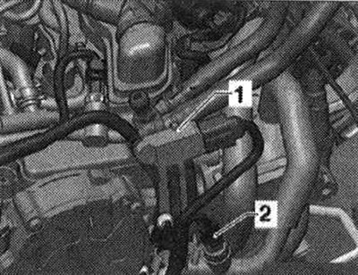
Unscrew the double clamp of the bracket. Unscrew the bracket of the pressure sensor from the vacuum pump, 2 nuts. Under the bracket of the pressure sensor there are 2 nuts, which should also be unscrewed. Remove the coolant pipe from the stud of the vacuum pump and press it aside. Remove the vacuum hose from the vacuum pump. Unscrew all bolts of the sealing flange of the vacuum pump. Remove the vacuum pump from the mount.
Installation
Replace the gaskets. Check that the gaskets are correctly positioned during installation. Rotate the vacuum pump drive so that it fits into the camshaft groove during installation. Install the vacuum pump. Screw in all the bolts on the sealing flange of the vacuum pump and tighten them. Screw in 2 nuts under the pressure sensor bracket and tighten. Install a new hose clamp on the vacuum hose. Connect the vacuum hose to the vacuum pump. Clamp the clamp with suitable pliers. Install the coolant pipe over the studs of the vacuum pump. Insert the bracket of the diesel particulate filter pressure sensor into the vacuum pump. Screw on the bracket. Secure the pressure sensor lines in the bracket. Screw in the pressure sensor. Install the engine casing.
Removal the vacuum pump of a 4-cyl. Turbo FSI engine
Before removing the vacuum pump, remove the high-pressure fuel pump. Do not remove the front wall of the water-diverting box. The vacuum pump is installed in the engine compartment backwards in the direction of travel "arrow".
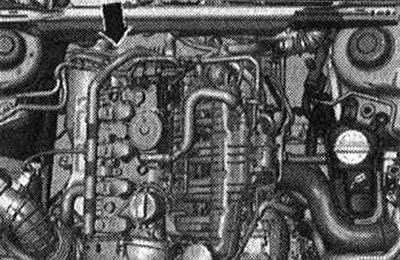
The petrol line is under pressure, do not disconnect it! Carefully remove the engine covers one by one from the mounting bolts. The vacuum pump is installed on the right side of the engine compartment, rearward in the direction of travel. Remove the small vacuum hose from the fuel line. Unscrew the fuel line bracket on the vacuum pump and the high-pressure fuel pump.
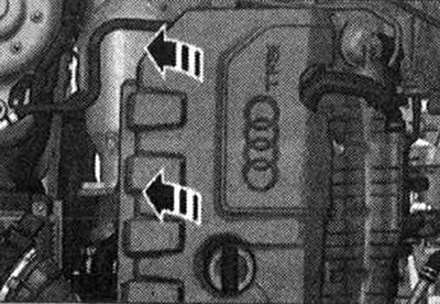
Disconnect the plug connector "1" of the high-pressure fuel pump. Remove the high-pressure fuel pump "2". Disconnect the vacuum hose from the hose clamp at the attachment point to the vacuum pump.
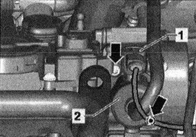
Be careful not to damage the vacuum hose. A damaged vacuum line must be replaced. Unscrew all the bolts of the vacuum pump sealing flange "arrows".
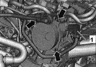
Do not disconnect the vacuum hose from the vacuum line "2" on the wall of the water drain box. Remove the vacuum pump from the mount.
Installation
Replace the gaskets. Check that the gaskets are correctly positioned during installation. Rotate the vacuum pump drive so that it fits into the camshaft groove during installation. Screw in all the "arrow" bolts of the vacuum pump sealing flange and tighten them. Install a new hose clamp on the vacuum hose. Install the vacuum hose on the vacuum pump branch pipe. Squeeze the hose clamp on the vacuum pump branch pipe using suitable pliers. Be careful not to damage the vacuum hose. A damaged vacuum line must be replaced. Install the high-pressure fuel pump. Screw in the fuel line bracket on the vacuum pump and high-pressure fuel pump. Connect the small vacuum hose to the fuel line. Connect the plug connector "1" of the high-pressure fuel pump. Install the engine casing.