
Table of contents: Mounting frame, tightening sequence ↓ Installation ↓
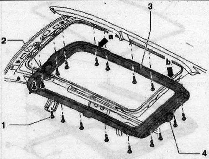
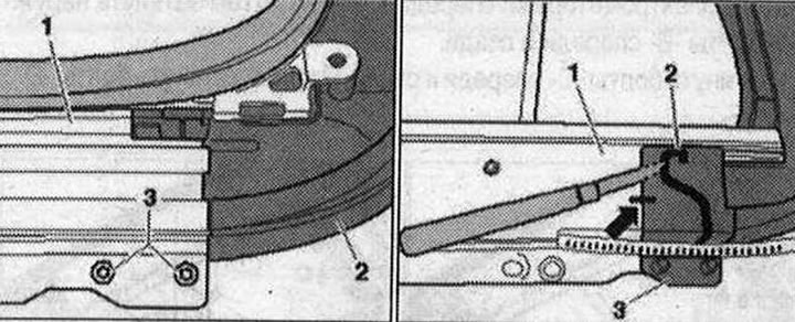
Details and assemblies of the hatch frame 1. Bolt. 8 Nm. When installing, follow the screwing sequence; 2. Used sliding sunroof "J245"; 3. Mounting frame. Removal: Removal of the frame must be carried out by at least two mechanics. Remove the headlining. Disconnect the water drain hoses from the "arrow" pipes of the mounting frame "3". Disconnect the connector of the sunroof control unit wires "J245" "2" and the curtain control unit "J394". Unscrew the bolts "1" from the mounting frame "3" and lift it out of the car with two people. Installation: lift the mounting frame into the car and screw in the bolts "2", but do not tighten them. Center the mounting frame, for example, with two 8 mm drills in the centering holes "6" and "7" relative to the roof. Tighten both outer front and rear bolts to the required torque; 4. Used sunblind "J394"
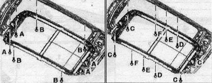
Mounting frame, tightening sequence
Be sure to tighten the bolts in the specified sequence and to the correct torque. First tighten the inner bolts "A" near the electric motors at the front and rear. Then tighten the outer bolts "B" at the front and rear.
Tighten the "C" bolts at the front and rear. Finally tighten the "D" bolts; "E" and "F".
Insert the rear part "2" completely together with the guide tubes "3" counterclockwise into the guide "1". Tighten the bolts "3" of the rear cover "1" of the guide rail "2" to a torque of 2 Nm.
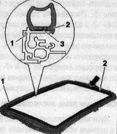
Before installation, it is recommended to check the tightness of the frame. Check the tightness of the drain pipe "1". Fill the indicated area "3" with water between the rear part "2" and the guide "4".
Wait 5 minutes and check for leaks. If necessary, seal leaks with butyl cord -AKD 497 010 04 R10-. Install the sunroof blind. Install the sunroof blind motor. Install a new inner seal. Reinstall the frame. After completing all work, initialize all sunroof drives.
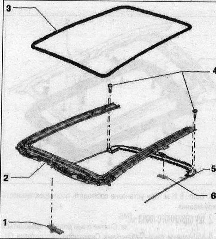
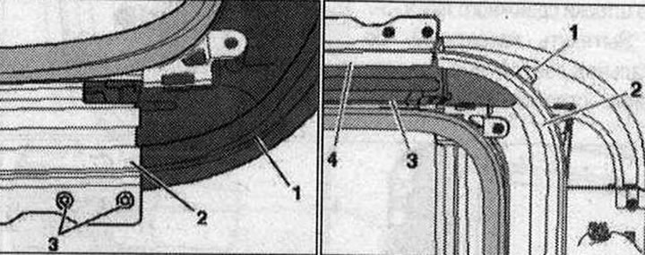
Removal the back cover 1. Front panel of the electric motor; 2. Mounting frame; 3. Inner seal; 4. Bolt 2 Nm; 5. Back cover; 6. Rear panel of the electric motor
Remove the frame. Remove the inner seal "2" from the frame "1". Remove the sunroof curtain. Remove the wiring harness from the rear cover.
Unscrew bolts "3" of the rear cover "2" from the guide "1".
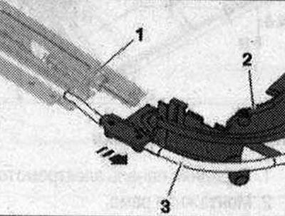
Mark the position of the "arrow" of the rear part "3" for subsequent installation. Using a knife, separate the adhesive joint "2" between the guide "1" and the rear part "3".
Remove the rear part "2" entirely together with the guide tubes "3" from the guide "1" in the direction of the "arrow".
Installation
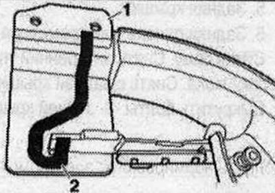
Remove adhesive residues using the "VAS 6349" nozzle. Wipe the bonding surfaces on the back and on the guides with solvent "D 009 401 04". Insert the butyl adhesive cord -AKD 497 010 04 R10 "-2" 0 3.5 mm into the adhesive channel of the cover, as shown in Fig. "1".