
Table of contents: Preparing the head for installation ↓ Installing the cylinder head ↓ Left cylinder head ↓ Both cylinder heads ↓
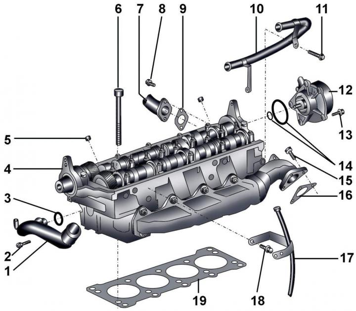
Fig. 3.4–52. Cylinder head: 1 – front middle pipe of the cooling system; 2 – bolt, 10 Nm; 3 – sealing ring; 4 – cylinder head; 5 – guide bushing; 6 – cylinder head mounting bolts; 7 – connecting pipe of the exhaust gas recirculation system; 8 – bolt, 10 Nm; 9 – gasket; 10 – crankcase ventilation pipe; 11 – bolt, 10 Nm; 12 – vacuum pump; 13 – bolt, 10 Nm; 14 – sealing rings; 15 – bolt, 20 Nm + turn further by 90°; 16 – gasket; 17 – guide tube for oil level indicator (dipstick); 18 – bolt, 10 Nm; 19 – cylinder head gasket
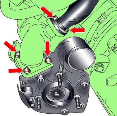
Fig. 3.4–53. Location of bolts securing the left exhaust gas recirculation pipe and turbocharger to the exhaust manifold
Loosen the bolts and disconnect the left EGR pipe (see Fig. 3.4–53).
Unscrew the bolts securing the turbocharger to the exhaust manifold (see Fig. 3.4–53).
Remove the fuel heat exchanger mounting bolts.
Disconnect the middle coolant pipe from the rear of the cylinder head.
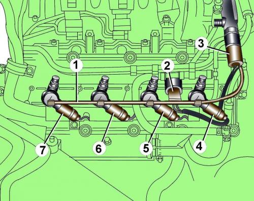
Fig. 3.4–50. Location of the fuel return line (1) and electrical connectors (2–7).
Disconnect the electrical connectors from the injectors (see Fig. 3.4–50).
Unscrew the wire fastening clamp and move the wires to the side (see Fig. 3.4–50).
Release the fuel supply line 1 from the clamps (see Fig. 3.4–50) and remove it from the injectors.
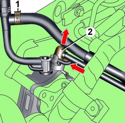
Fig. 3.4–51. Location of the clamp (1) for fastening the fuel hose to the T-shaped branch and fastening the fuel line (2) to the fuel supply pump
Loosen the clamp and remove the fuel hose from the T-piece (see Fig. 3.4–51).
Remove the spring clip and disconnect the fuel line from the fuel supply pump (see Fig. 3.4–51).
Disconnect the fuel lines near the right cylinder head cover.
Unscrew the oil filler cap.
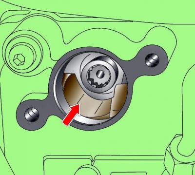
Fig. 3.4–43. Location of the notch in the oil filler neck opening
Using the crankshaft pulley mounting bolt, turn the shaft until a recess is visible in the oil filler neck hole (see Fig. 3.4–43).
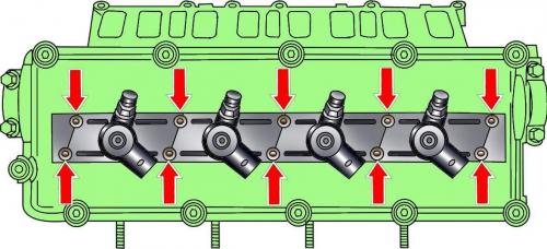
Fig. 3.4–44. Location of fuel injector housing mounting bolts
Loosen the injector housing mounting bolts, pull the housings upwards and turn them 90° counterclockwise (see Fig. 3.4–44).
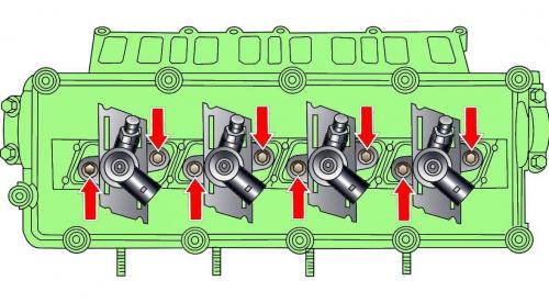
Fig. 3.4–45. Location of fuel injector mounting bolts
Unscrew the exposed injector mounting bolts (see Fig. 3.4–45).
Pull up and remove the injectors for cylinders 1 and 3. You can use a lever to remove the injectors.
Turn the crankshaft clockwise 180° and remove the injectors of cylinders 2 and 4.
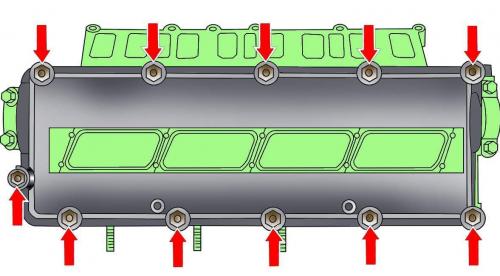
Fig. 3.4–46. Location of cylinder head cover mounting bolts
Unscrew the bolts and remove the right cylinder head cover (see Fig. 3.4–46).
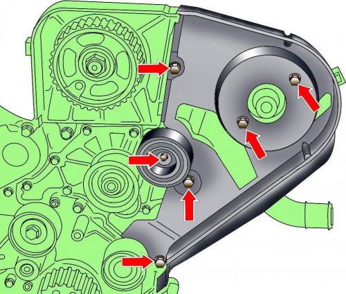
Fig. 3.4–55. Location of guide roller and rear toothed belt cover mounting bolts
Unscrew the bolts and remove the rear timing belt covers (see Fig. 3.4–55, 3.4–58).
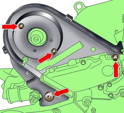
Fig. 3.4–58. Location of rear timing belt cover mounting bolts
Disconnect the fuel lines from the injection pump.
Disconnect the electrical connector from the coolant temperature sensor.
Unscrew the bolts and remove the middle pipe of the cooling system.
Unscrew the bolts and remove the right cylinder head cover (see Fig. 3.4–46).
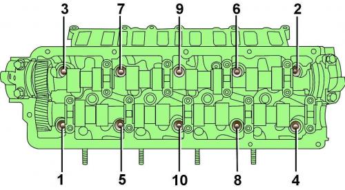
Fig. 3.4–57. Location and tightening sequence of cylinder head bolts
Unscrew the bolts and remove the right cylinder head (Fig. 3.4–57).
Preparing the head for installation
The mating surfaces of the cylinder head and block must be completely clean. Use a hard plastic or wooden scraper to clean them. Be careful when cleaning, as the aluminum alloy is very easy to damage. Check that carbon deposits do not get into the oil channels and cooling system channels. This is especially important for the lubrication system, as carbon deposits can block the oil supply to engine parts. Clean the channels if necessary.
Check the mating surfaces of the cylinder head and block for nicks, deep scratches and other damage. Minor defects can be eliminated by mechanical treatment. In case of significant defects, replace the parts.
Clean the bolt holes in the block. Screwing a bolt into an oil-filled hole can cause the block to burst due to excessive hydraulic pressure.
Installing the cylinder head
When installing, it is necessary to use new cylinder head mounting bolts.
All clamps and collars that were damaged or cut during engine removal must be replaced with new ones.
When installing, replace the self-locking nuts and bolts, which were tightened by turning them to a certain angle, with new ones, as well as the sealing rings and gaskets.
Check the flatness of the cylinder head mating surface.
When replacing the cylinder head and its gasket, it is necessary to fill the cooling system with fresh coolant.
The new cylinder head gasket must be removed from the packaging immediately prior to installation.
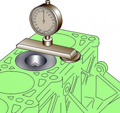
Fig. 3.4–59. Measuring the piston protrusion from the cylinder block
If new pistons are installed on the engine, it is necessary to measure the piston protrusion from the cylinder block (Fig. 3.4–59).
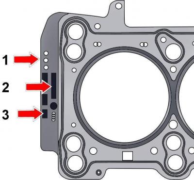
Fig. 3.4–60. Marking the cylinder head cover gasket with holes (1), number (2) and installation side (3)
Based on the amount of piston protrusion, the thickness of the new cylinder head gasket is selected (Fig. 3.4–60).
| Piston protrusion, mm | Number of holes |
| 0,39–0,49 | 1 |
| 0,49–0,54 | 2 |
| 0,54–0,65 | 3 |
Place the gasket on the guide pins with the "oben" lettering facing the head.
If work has been done on the valve train, turn the engine over manually two full revolutions to ensure that the pistons have not struck the valves.
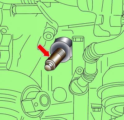
Fig. 3.4–61. Location of the 3242 set screw for fixing the crankshaft
Before installing the cylinder head, set the piston of the first cylinder and the camshaft to TDC of the compression stroke. Fix the crankshaft in this position. To fix the crankshaft from the cylinder block, unscrew the fuel injection timing sensor and screw in the adjusting screw 3242 instead (Fig. 3.4–61).
Using a screwdriver blade as a lever, remove the cover that covers the end of the camshaft on the cylinder head.
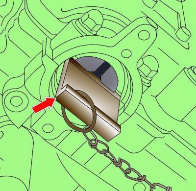
Fig. 3.4–36. Location of camshaft positioning pin 3458
Install retainer 3458 instead of the cover, which determines the initial position of the camshaft (see Fig. 3.4–36).
Insert the cylinder head mounting bolts and tighten them by hand.
In the sequence shown in Figure 3.4–57, tighten the cylinder head bolts in four stages:
- 1st - torque 35 Nm;
- 2nd - torque 60 Nm;
- 3rd - turn to an angle of 90°;
- 4th - turn to an angle of 90°
Further tightening of the cylinder head mounting bolts is not required.
Left cylinder head
When installing the guide pipe for the oil level indicator (dipstick), a new O-ring must be installed.
Both cylinder heads
Install the timing belt.
Install the cylinder head cover.
Fill with fresh coolant.
Connect the ground wire to the battery.
Turn on radio and enter the code into it.
Raise the power windows all the way up. Then press all power window switches again for at least 1 second to the closed position to activate the power window control unit.
Set the time on the clock.