



Table of contents: Removal ↓ Installation ↓
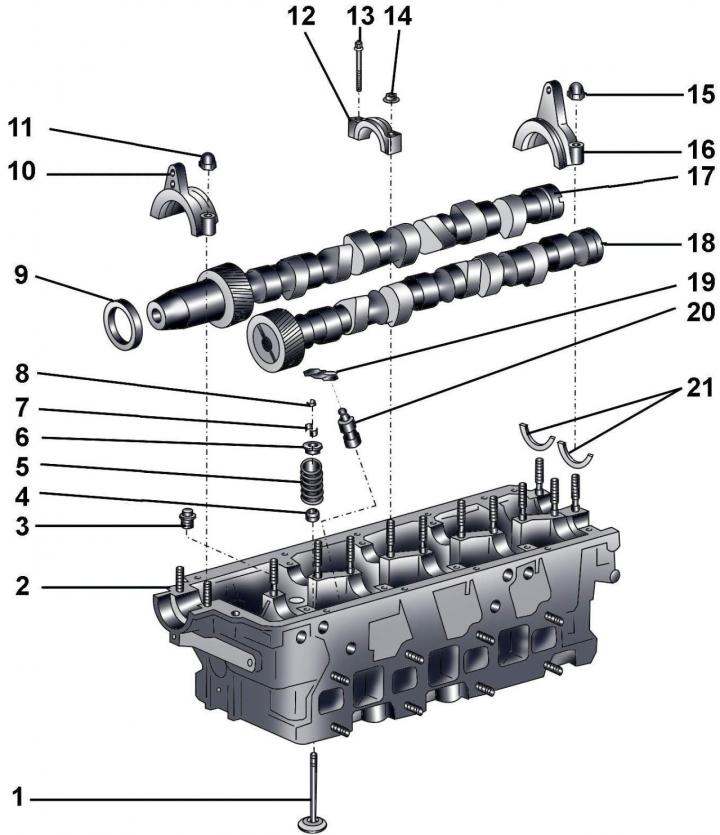
Fig. 3.4–62. Valve mechanism: 1 – valve; 2 – cylinder head; 3 – pressure limiting valve 2.7 bar, 25 Nm; 4 – oil deflector cap; 5 – valve spring; 6 – valve spring plate; 7 – crackers; 8 – lever support; 9 – sealing ring; 10 – Front cover of the intake camshaft bearing; 11 – cap nut, 15 Nm; 12 – bearing cover; 13 – bolt, 10 Nm; 14 – nut, 10 Nm; 15 – cap nut, 15 Nm; 16 – rear cover of the exhaust camshaft bearing; 17 – intake camshaft; 18 – exhaust camshaft; 19 – lever; 20 – hydraulic pusher; 21 – thrust half rings
Before installation, it is necessary to lubricate the working surfaces of the hydraulic tappets 20 (Fig. 3.4–62) with engine oil.
Removal
Before disconnecting the battery, find out if you have a radio activation code.
Turn off the ignition and disconnect the ground wire from the battery.
Remove the cylinder head cover.
Remove the timing belt from the camshaft pulleys.
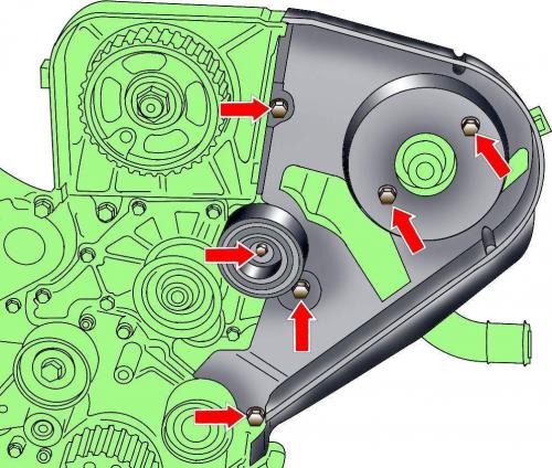
Fig. 3.4–55. Location of guide roller and rear toothed belt cover mounting bolts
Unscrew the bolts and remove the rear timing belt covers (see Fig. 3.4–55, 3.4–58).
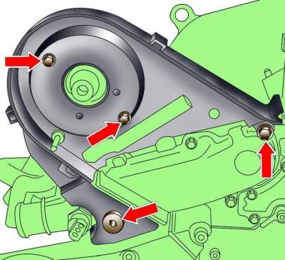
Fig. 3.4–58. Location of rear timing belt cover mounting bolts
Unscrew the front and rear camshaft bearing caps of the inlet valves (see Fig. 3.4–62).
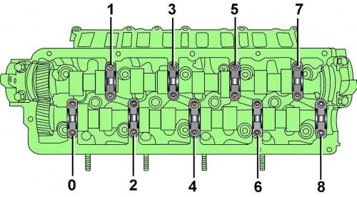
Fig. 3.4–63. Location of nuts and bolts for fastening camshaft bearing caps
Unscrew the bearing caps 0, 3, 4, 7 and 8 of the camshafts (Fig. 3.4–63).
Gradually unscrew bearing caps 2 and 6 crosswise and remove the exhaust camshaft.
Gradually unscrew bearing caps 1 and 5 crosswise and remove the intake camshaft.
Installation
Make sure the crankshaft is secured with set screw 3242.
Unscrew the stud located at the end of the camshaft from the cylinder head.
Make sure the thrust washers are in place.
Check the condition and position of the rocker arms and hydraulic tappets.
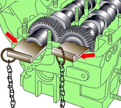
Fig. 3.4–64. Using tool 3458 to correctly install camshafts
Install the intake camshaft in place so that tool 3458 can be installed into the end of the shaft (Fig. 3.4–64).
Install bearing caps 1 and 5 and secure them with bolts.
Install bearing caps 2 and 6 and secure them with bolts.
Install bearing caps 0, 3, 4, 7, 8 and secure them with bolts.
Recheck the position of the rocker arms and hydraulic lifters.
Clean the mating surfaces on the cylinder head and camshaft outer caps.
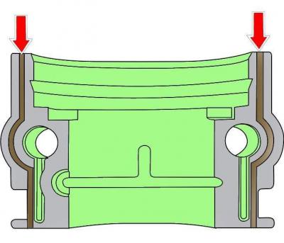
Fig. 3.4–65. Place where the sealant layer is applied to the right inner rear cover
Apply a thin layer of sealant to the mating surface of the right inner rear cover (Fig. 3.4–65).
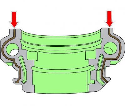
Fig. 3.4–66. Place where a layer of sealant is applied to the outer rear or front right cover.
Apply a thin layer of sealant to the mating surface of the outer rear or front right cover (see Fig. 3.4–66).
Install the outer covers.
Further installation is carried out in the reverse order of removal.
Install the cylinder head cover.
Install the timing belt.
Wait 30 minutes before starting the engine: the hydraulic tappets must return to normal condition, otherwise the pistons may hit the valves.
(The original version is on the portal: AUDIMANUAL.ru)