
Withdrawal
Open the cap of the expansion tank.
Remove the front cross member.
Install a coolant drip tray under the engine.
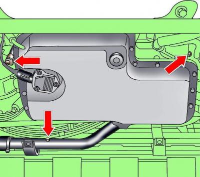
Pic. 3.4–17. Location of threaded plugs for draining the coolant from the cooling system
Unscrew the three screw plugs and drain the coolant from the cooling system (see fig. 3.4–17).
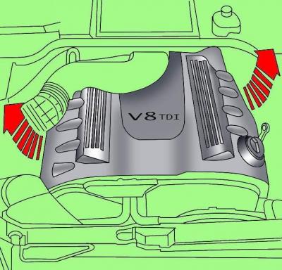
Pic. 3.4–19. Removing the engine cover
Pull the sides up to remove the engine cover (see fig. 3.4–19).
Turn away screws and remove an additional left casing in a motor compartment.
Loosen the mounting clamps and disconnect the cooling system hoses near the high pressure fuel pump.
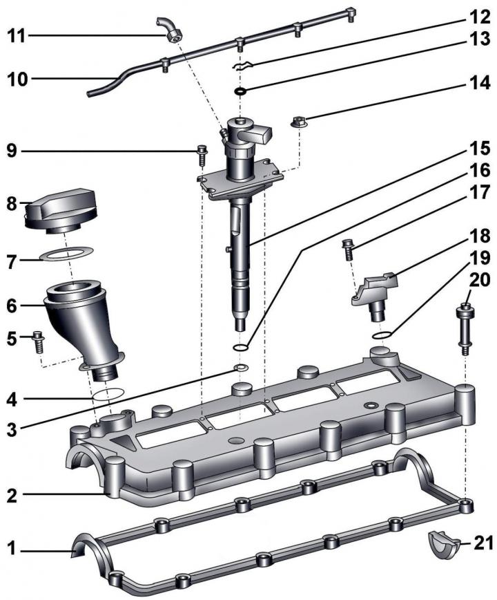
Pic. 3.4–40. Cylinder head cover: 1 – a lining of a cover of a head of the block of cylinders; 2 – a cover of a head of the block of cylinders; 3, 4 - sealing rings; 5 - bolt, 10 Nm; 6 - oil filler neck; 7 - seal; 8 - cover; 9 - bolt, 5 Nm; 10 - fuel supply line; 11 - high pressure fuel line; 12 - spring clip; 13 - sealing ring; 14 - bolt, 10 Nm; 15 - fuel injector; 16 - sealing ring; 17 - bolt, 10 Nm; 18 - Hall sensor G40; 19 - sealing ring; 20 - bolt, 10 Nm; 21 - plug
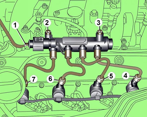
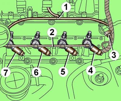
Pic. 3.4–41. Arrangement of bolts and connecting nuts for fastening pipelines to the fuel injection control unit (rail element): 1 - face connecting nut; 2, 3 - bolts; 4, 5, 6, 7 - connecting nuts of fuel lines
Unscrew the end connection nut 1 (pic. 3.4–41).
Unscrew the connecting nuts of the fuel lines 4-7.
Unscrew two bolts 2 and 3 and remove the fuel injection unit from the intake manifold.
Pic. 3.4–42. Vacuum hose location (1), fuel return line clamps (2) and electrical connectors for injectors (3, 4, 5, 6, 7)
Disconnect the electrical connectors of the injectors 3-7 (pic. 3.4–42).
Disconnect vacuum hose 1.
Release from clips a returnable fuel line 2 and remove it.
Unscrew the oil filler cap.
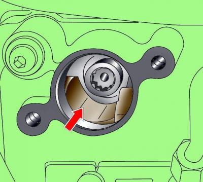
Pic. 3.4–43. The location of the notch in the oil filler hole
At the crankshaft pulley bolt, turn the shaft until a notch is visible in the oil filler hole (pic. 3.4–43).
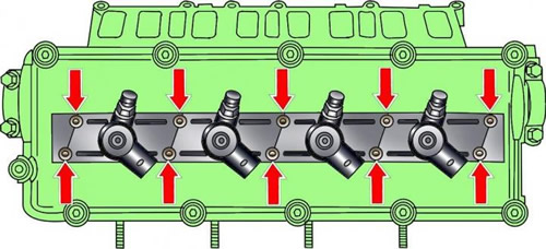
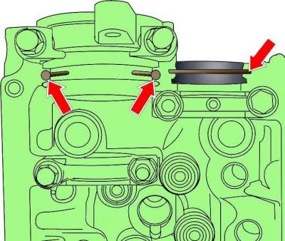
Pic. 3.4–44. Arrangement of bolts of fastening of casings of fuel atomizers
Unscrew the bolts securing the injector shrouds, pull the shrouds up and turn 90°counterclockwise (pic. 3.4–44).
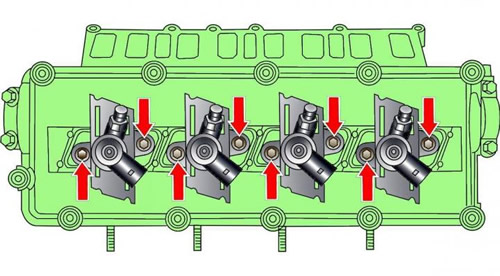
Pic. 3.4–45. Location of fuel injector mounting bolts
Unscrew the exposed injector mounting bolts (pic. 3.4–45).
Pull up and remove injectors for cylinders 6 and 8.
When removing the fuel injectors, you can use the lever.
Turn the crankshaft clockwise 180°and remove the injectors of cylinders 5 and 7.
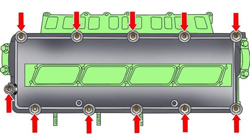
Pic. 3.4–46. Arrangement of bolts of fastening of a cover of a head of the block of cylinders
Turn out bolts and remove the left cover of a head of the block of cylinders (pic. 3.4–46).
Installation
Installation is carried out in the reverse order of removal, taking into account the following.
Replace O-rings on fuel return pipes.
If necessary, replace the cylinder head cover gasket.
Install the sealing ring.
Degrease the surface under the cylinder head cover gasket.
Pic. 3.4–47. Places for applying sealant before installing the left cylinder head cover
Apply a thin, continuous layer of sealant to the semi-circular surface (pic. 3.4–47) at the end of the cylinder head.
Apply a 3 mm diameter layer of sealant in 5 mm projection lengths to the outer camshaft covers (see fig. 3.4–47).
Tighten nuts of fastening of a cover of a head of the block of cylinders gradually crosswise.
Install the front cross member.
Pour coolant into the cooling system.
Visitor comments