
Withdrawal
Turn the crankshaft in the direction of working rotation by the pulley mounting bolt until the piston of the fifth cylinder is set to the TDC of the compression stroke.
Remove poly V-belt.
Release the wires from the clamps on the radiator fan shroud, unscrew the mounting screws and remove the electric radiator fan.
Remove vibration damper from the crankshaft pulley.
Remove the front toothed belt covers.
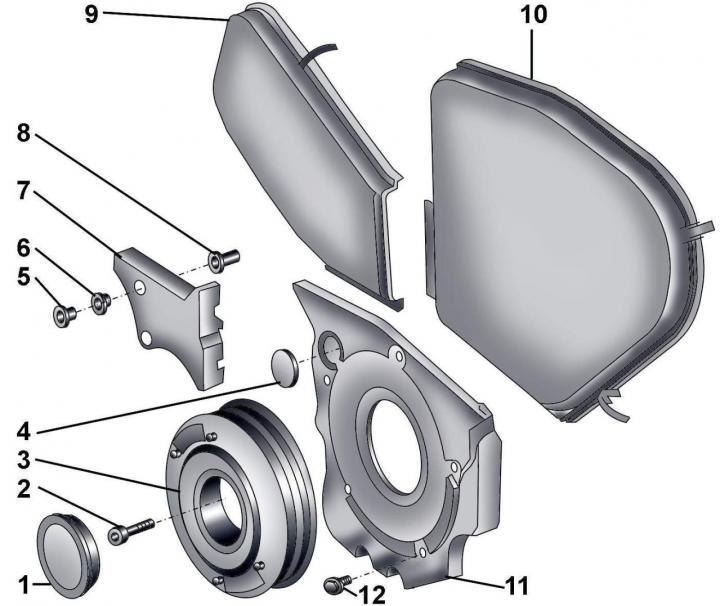
Pic. 3.4–27. Toothed belt guards: 1 - casing; 2 - bolt, 22 Nm; 3 - vibration damper with poly V-belt pulley; 4 - plug of the lower casing; 5 - bolt, 10 Nm; 6 - rubber bushing; 7 - casing; 8 - mounting sleeve; 9 - front right casing; 10 - front left casing; 11 - lower casing; 12 - bolt, 10 Nm
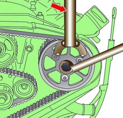
Pic. 3.4–29. Using special tool 3036 to prevent the camshaft pulley from turning
Alternately, using special tool 3036 (pic. 3.4–29), secure the camshaft pulley from turning and unscrew it three turns (but do not unscrew completely) camshaft pulley bolt.
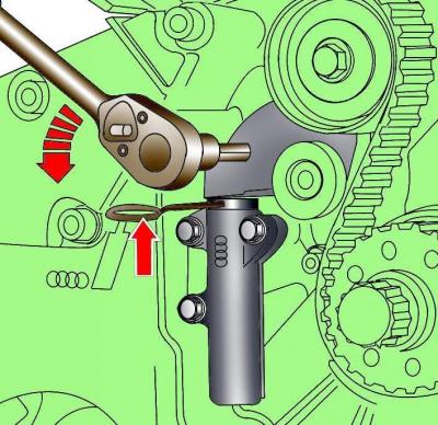
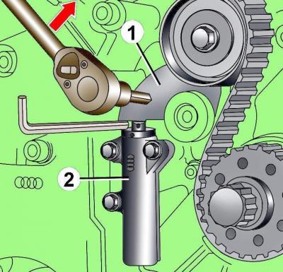
Pic. 3.4–30. Loosening the tension of the toothed belt and fixing the tension mechanism with tool T40011
Using an 8 mm socket wrench, turn the tension roller counterclockwise and fix it in this position with tool T40011 (pic. 3.4–30).
Chalk, marker or paint mark the direction of rotation of the toothed belt. If a used toothed belt rotates in the opposite direction when a used toothed belt is installed, it will break.
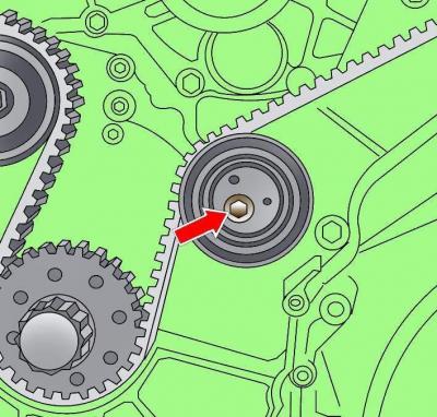
Pic. 3.4–31. The location of the bolt fastening the roller with an eccentric
Loosen the fastening bolt of the eccentric roller (pic. 3.4–31).
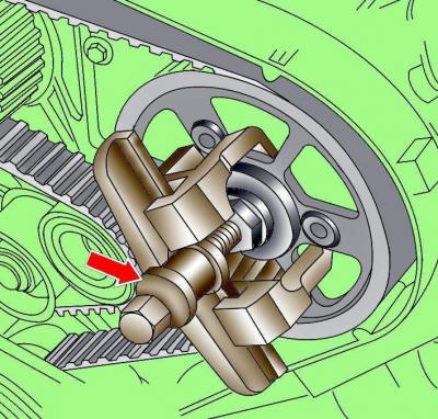
Pic. 3.4–32. Using the T40001 puller to remove the timing belt pulley from the camshaft
Using puller T40001 (pic. 3.4–32), remove both camshaft pulleys from their mounting cones. When removing the pulleys, the puller must rest against the bolts of the camshaft pulleys. The camshaft pulleys must rotate freely, but not dangle on their mounting cones.
Turn out a bolt of fastening of a pulley of the right camshaft and remove a gear belt together with a pulley.
Installation
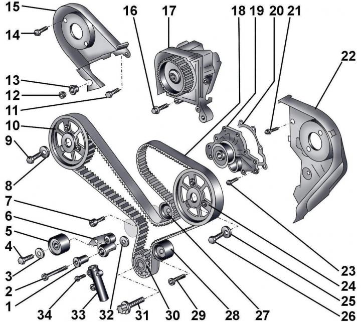
Pic. 3.4–28. Toothed belt: 1 - bushing; 2 - bolt, 45 Nm; 3 – a washer of a tension roller; 4 - bolt, 45 Nm; 5 - tension roller; 6 - tension roller lever; 7 - bolt, 70 Nm; 8 - washer; 9 - bolt, 75 Nm; 10 – a pulley of a gear belt of a camshaft of inlet valves; 11 - bolt, 22 Nm; 12 - bolt, 10 Nm; 13 - rubber bushing; 14 - bolt, 10 Nm; 15 – a back right casing of a gear belt; 16 - bolt, 22 Nm; 17 - high pressure fuel pump; 18 - toothed belt; 19 - water pump; 20 - gasket; 21 - bolt, 10 Nm; 22 – a casing of a gear belt behind at the left; 23 - bolt, 10 Nm; 24 – a pulley of a gear belt of a camshaft of final valves; 25 - washer; 26 - bolt, 75 Nm; 27 - guide roller; 28 - roller with an eccentric; 29 - bolt, 45 Nm; 30 – a pulley of a gear belt of a cranked shaft; 31 – bolt, 200 Nm + tighten by 180°; 32 - washer of the tension lever; 33 – toothed belt tensioner; 34 - bolt, 10 Nm
When installing a toothed belt, use a new gasket 20 (see fig. 3.4–28) and bolt 31.
Check that the position of the camshafts is fixed with the clamps 3458, and the crankshaft is fixed with the set screw 3242.
The camshaft pulleys must turn freely.
Install the toothed belt on the pulleys in the following sequence:
- crankshaft;
- tension roller;
- roller with an eccentric;
- left camshaft;
- high pressure fuel pump;
- guide roller;
- water pump;
- right camshaft pulley, then install the pulley on the camshaft.
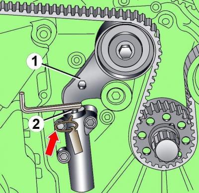
Pic. 3.4–33. Installing a 4mm hex wrench between the idler pulley arm (1) and tension mechanism (2)
Insert a 4mm hex wrench between tensioner and idler arm (pic. 3.4–33).
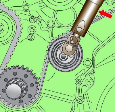
Pic. 3.4–34. Using the special tool T4009 to tension the toothed belt by turning the eccentric roller
Using a special tool that fits into the two holes of the eccentric roller, turn the roller counterclockwise to a torque of 3 Nm and in this position tighten the roller mounting bolt to a torque of 45 Nm (pic. 3.4–34).
Remove the hex wrench located between the tension mechanism and the tension roller arm.
Using an 8 mm socket wrench, turn the toothed belt tensioner pulley counterclockwise and make sure that tool T40011 can be installed in this position (see fig. 3.4–30).
Pic. 3.4–35. Turning the tension roller lever (1) for removing the 4 mm hex key from the tensioner (2)
Using an 8mm socket wrench, turn the timing belt tensioner pulley clockwise, remove the hex key located between the tensioner and idler arm, and check that the tensioner plunger presses the idler arm (pic. 3.4–35).
Tighten the camshaft pulley bolts, holding the pulleys from turning with tool 3036.
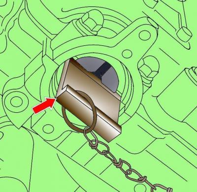
Pic. 3.4–36. The location of the retainer 3458, which determines the position of the camshaft
Remove set screw 3242 and retainers 3458 and rotate the crankshaft two turns, set it to the TDC position of the fifth compression stroke cylinder and check the installation of the crankshaft and camshafts. To check the position of the crankshaft from the cylinder block, unscrew the plug and screw in set screw 3242 instead (pic. 3.4–36). If set screw 3242 and retainers 3458 are seated, then the crankshaft and camshafts are installed correctly.
Further installation is carried out in the reverse order of removal, taking into account the following.
Install a vacuum pump on the left cylinder head.
Install poly V-belt.
Pour coolant into the cooling system.
Note:
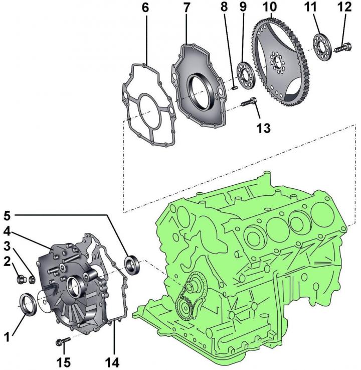
Pic. 3.4–37. Front and rear cylinder block covers: 1 - sealing ring; 2 - screw plug, 22.5 Nm; 3 - sealing ring; 4 - front cover; 5 - thrust ring; 6 - gasket; 7 - back cover with a sealing ring; 8 - centering sleeve; 9 - support washer; 10 - leading disk; 11 - washer; 12 – bolt, 60 Nm + tighten by 180°; 13 - bolt, 10 Nm; 14 - gasket; 15 - bolt, 10 Nm
When installing it is necessary to use a new sealing ring 3 (pic. 3.4–37), gaskets 6, 14 and bolts 12.
Visitor comments