
Recommendations for removing the engine
Read the entire section before removing the engine.
If the engine is removed for repair, it is necessary first of all to select a place for work, provide space for maintenance and storage of spare parts. It is recommended that the engine be repaired at a workshop or in a garage with a flat, horizontal floor with a clean hard surface.
Before removing the engine, flush the engine and engine compartment. To remove the engine, use a lifting device that allows you to safely lift the power package.
If you are removing the engine for the first time, you must invite an experienced specialist. Some work should be done with an assistant.
Warning: All clips and clamps that will be damaged or cut when removing the engine must be replaced with new ones when assembling the engine.
The engine is removed forward without a gearbox.
Drained coolant must be collected and disposed of.
Before disconnecting the battery, find out if you have a radio activation code.
Withdrawal
Turn off the ignition and disconnect the wire «masses» from the battery.
Remove the front cross member.
Loosen the screws and remove the protective cover located behind the air filter.
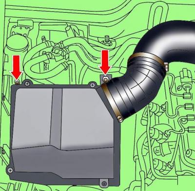
Pic. 3.4–1. Clamp location (1) fixing the air pipe and air filter fixing screws
Loosen the clamps and remove the air pipe connecting the air filter and the air pipe (pic. 3.4–1).
Loosen the air filter housing screws.

Pic. 3.4–2. Location of air pipe fixing screws
Loosen the screws and remove the air pipe (pic. 3.4–2).
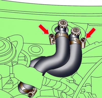
Pic. 3.4–3. Location of the clamps for fastening the cooling system hoses to the heater fittings on the bulkhead of the engine compartment
Loosen the clamps (pic. 3.4–3) and disconnect the coolant hoses going to the heater.
Disconnect the vacuum hose and gray electrical connector located near the heater fittings on the bulkhead of the engine compartment, and take them aside.
Loosen the clamp and disconnect the coolant hose from the fitting behind the fuel pump.
Loosen the clamps and remove the hoses from the distribution pipeline.
Loosen the clamps, remove the crankcase ventilation hoses and take them to the side.
Turn out a bolt and remove the delivery pipeline from the power steering pump.
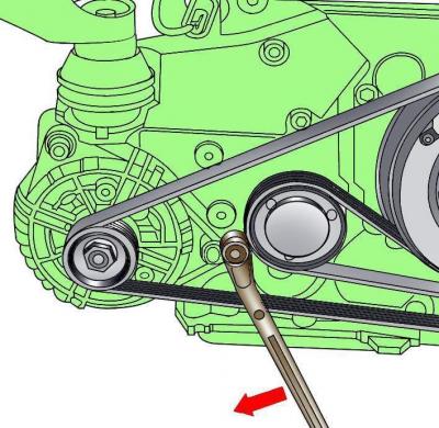
Pic. 3.4–4. Releasing tension on the V-ribbed belt
Loosen the poly V-belt tension by turning the tensioner clockwise with the wrench (pic. 3.4–4).
Remove poly V-belt.
Loosen the clamps and disconnect the cooling system hoses from the engine.
Loosen the clamps and disconnect the fuel supply line from the T-piece.
Turn out screws and remove a casing of the block of management of the engine. Release the spring clips and remove the baffle seal at the rear of the engine compartment.
Remove the protective covers at the rear of the engine compartment.
Lift up the left cover covering the control box and remove the rear right screw.
Loosen the remaining fixing screws.
Remove the control box cover.
Disconnect the electrical connectors from the engine control unit and the transmission control unit, as well as all electrical connectors on the bulkhead of the engine compartment.
Turn out screws and remove the basis of the block of management of the engine.
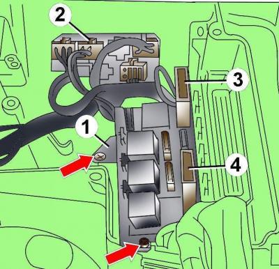
Pic. 3.4–5. Screw location (1) fixing the relay block, electrical connector (2) and fuse boxes (3, 4)
Remove screws 1 and remove the relay box (pic. 3.4–5).
Disconnect an electric socket 2 and remove cases 3 and 4 fuses.
Unscrew the clip securing the wires to the bulkhead of the engine compartment and take the wires to the side.
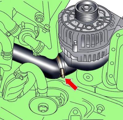
Pic. 3.4–6. Arrangement of a collar of fastening of an air branch pipe to the generator
Loosen the clamp and disconnect the air pipe from the generator (pic. 3.4–6).
Disconnect the green electrical connector from the electromagnetic clutch, release the retainer and move the wires to the side.
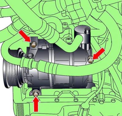
Pic. 3.4–7. Arrangement of bolts of fastening of the compressor of the conditioner to an arm
Unscrew the bolts securing the air conditioning compressor to the bracket, then, without disconnecting the pipelines from the compressor, move it to the side and fix it on the body (pic. 3.4–7).
Disconnect the electrical connectors and unscrew the vehicle height sensor bracket under the left front wheel arch.
Unscrew the bolts and remove the protective casings of the drive shafts.
In the right part of the engine compartment, disconnect the electrical connectors, release the wire holders, unscrew the nut that secures the lug of the wire connection to «weight» and move the wires to the side.
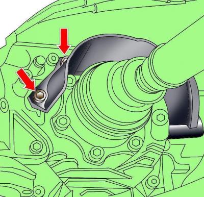
Pic. 3.4–8. Arrangement of bolts of fastening of the thermofilter of a shaft of a drive
Unscrew the mounting bolts and remove the heat shields of the right and left drive shafts (pic. 3.4–8).
Unscrew the drive shafts from the gearbox flanges.
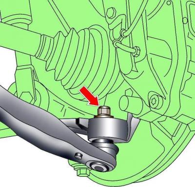
Pic. 3.4–9. Arrangement of a nut with a shoulder of fastening of a pin of a spherical hinge of the lower arm of a forward suspension bracket
Remove the collared nut securing the ball joint pin of the lower front suspension arm. Using a ball joint remover, remove the lower arm ball joint pin from the steering knuckle (pic. 3.4–9).
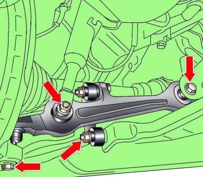
Pic. 3.4–10. Arrangement of nuts and a bolt of fastening of the lower arm of a forward suspension bracket
Turn out nuts and bolts of fastening of the lower arm of a forward suspension bracket and remove it from an arm (pic. 3.4–10).
Move the steering knuckles away from the car and secure the drive shafts to the car body with soft wire.
Unscrew the bolt securing the exhaust pipe hanger to the bracket.
Unscrew the connecting bolts of fastening of the left exhaust pipe.
Unscrew nuts of fastening of connecting clips of exhaust pipes and remove the left and right catalytic converters.
Unscrew the bolts and remove the heat shield of the cardan shaft.
Unscrew the propeller shaft flange mounting bolts, move the propeller shaft to the main gear and place it on the cross beam.
Unscrew the heat shield of the automatic transmission control cable.
Disconnect the automatic transmission control cable after setting the selector lever to the position «P», and turn the cable connector clockwise.
Unscrew the bolts and remove the front bracket of the lower mudguard of the engine compartment.
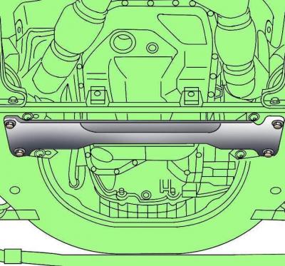
Pic. 3.4–11. Rear bracket for the lower mudguard of the engine compartment
Unscrew the bolts and remove the rear bracket of the lower mudguard of the engine compartment (pic. 3.4–11).
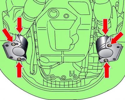
Pic. 3.4–12. Arrangement of nuts and bolts of fastening of supports of the power unit
Turn out six nuts and bolts of fastening of supports of the power unit (pic. 3.4–12).
Hook the load handlers onto the power unit and lift just enough so that the weight of the power unit is supported by the load handler.
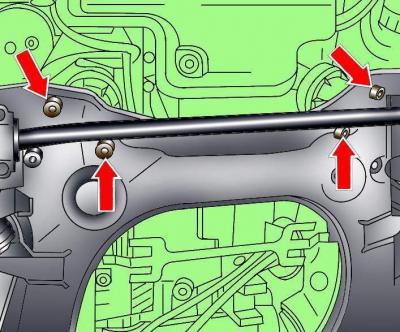
Pic. 3.4–13. The location of the engine mounting bolts to the lower frame
Remove the bottom bolts (pic. 3.4–13) fastening the engine to the lower frame. Make sure all electrical wires, hoses, fittings and pipes are disconnected from the engine.
Turn out three bolts of fastening of the torque compensator.
Lift the power unit and remove it forward from the engine compartment.
Installation
Installation is carried out in the reverse order of removal, taking into account the following.
When installing the engine, it is necessary to replace it with new self-locking nuts and bolts, which were tightened by additional turning to a certain angle, as well as sealing rings and gaskets.
When installing, check for the presence of centering bushings that determine the relative position of the engine and gearbox.
When connecting the engine to the gearbox, be careful not to damage engine speed sensor.
To attach the torque converter to the drive plate, bolts of the original design must be used.
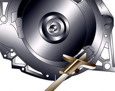
Pic. 3.4–14. Measuring the distance between the bearing surface for the torque converter mounting bolts and the bearing surface of the crankcase
Check the correct installation of the torque converter. If the distance between the bearing surface for the torque converter mounting bolts and the surface of the crankcase is 19 mm, then the torque converter is installed correctly. With an incorrectly installed torque converter, this distance is about 22 mm (pic. 3.4–14), while destroying the leading part of the torque converter and the automatic transmission pump.
Reinstall the engine and rock it from side to side to ensure it is properly supported on its supports.
Install cardan shaft.
Install and adjust the automatic transmission control cable.
Fill the cooling system with coolant. Coolant must not be reused if the cylinder head has been removed or the cylinder block has been replaced.
Check whether the elements of the exhaust system are correctly installed on the suspensions and whether they touch the body when rocking.
Fill the power steering system with oil and bleed air from it.
Fill the engine with oil.
Check that the electrical connectors are connected correctly.
Install the air conditioning compressor.
Install and adjust the tension of the V-ribbed belt.
Install the front cross member.
Connect wire «masses» to the battery.
Turn on radio and enter the code into it.
Raise the windows with the power windows up to the stop. Then press all power window switches again for at least 1 second to the closed position to activate the power window control unit.
Set the time on the clock.
Before starting the engine, check the presence and level of oil in the engine.
Visitor comments