
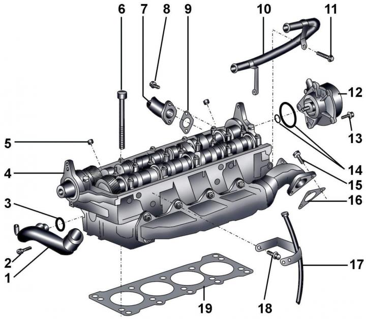
Pic. 3.4–52. Cylinder head: 1 - front middle pipe of the cooling system; 2 - bolt, 10 Nm; 3 - sealing ring; 4 – a head of the block of cylinders; 5 - guide sleeve; 6 – bolts of fastening of a head of the block of cylinders; 7 - connecting pipe of the exhaust gas recirculation system; 8 - bolt, 10 Nm; 9 - gasket; 10 - pipe of the crankcase ventilation system; 11 - bolt, 10 Nm; 12 - vacuum pump; 13 - bolt, 10 Nm; 14 - sealing rings; 15 – bolt, 20 Nm + tighten by 90°; 16 - gasket; 17 - guide pipe for the pointer (probe) oil level; 18 - bolt, 10 Nm; 19 – a lining of a head of the block of cylinders
Loosen the clamp, unscrew the bolt and remove the left air pipe.
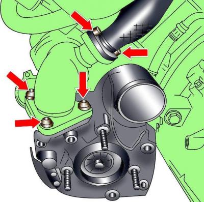
Pic. 3.4–53. Arrangement of bolts of fastening of the left pipe of recirculation of the fulfilled gases and a turbocharger to an exhaust manifold
Unscrew the bolts and disconnect the left EGR pipe (pic. 3.4–53).
Remove bolts securing turbocharger to exhaust manifold (see fig. 3.4–53).
Turn out a bolt of fastening of a directing pipe of the index (probe) oil level to the cylinder head.
Unscrew bolts of fastening of the fuel heat exchanger.
Unscrew and remove the middle pipe of the cooling system located behind the cylinder head.
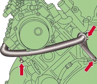
Pic. 3.4–54. Location of crankcase ventilation hoses
Unscrew and remove crankcase ventilation hoses (pic. 3.4–54).
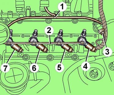
Pic. 3.4–42. Vacuum hose location (1), fuel return line clamps (2) and electrical connectors for injectors (3, 4, 5, 6, 7)
Disconnect the electrical connectors of the injectors 3-7 (see fig. 3.4–42).
Disconnect vacuum hose 1.
Release the fuel supply line 2 from the clamps and remove it.
Unscrew the oil filler cap.
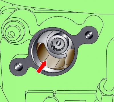
Pic. 3.4–43. The location of the notch in the oil filler hole
At the crankshaft pulley bolt, turn the shaft until a notch is visible in the oil filler hole (see fig. 3.4–43).
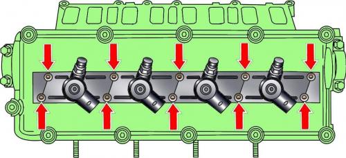
Pic. 3.4–44. Arrangement of bolts of fastening of casings of fuel atomizers
Unscrew the bolts securing the injector shrouds, pull the shrouds up and turn them 90°counterclockwise (see fig. 3.4–44).
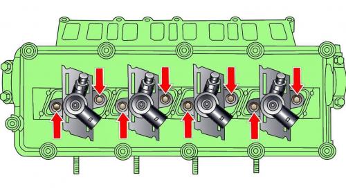
Pic. 3.4–45. Location of fuel injector mounting bolts
Loosen the exposed fuel injector bolts (see fig. 3.4–45).
Pull up and remove the injectors of cylinders 6 and 8. When removing the injectors, you can use the lever.
Rotate the crankshaft clockwise 180°and remove the fuel injectors for cylinders 5 and 7.
Remove the toothed belt.
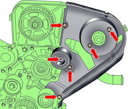
Pic. 3.4–55. Arrangement of bolts of fastening of a directing roller and a back casing of a gear belt
Turn out a bolt of fastening of the directing roller (pic. 3.4–55).
Unscrew bolts and remove a back casing of a gear belt (see fig. 3.4–55).
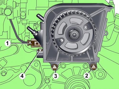
Pic. 3.4–56. Electrical connector location (1) and bolts (2, 3, 4) injection pump mountings
Disconnect from high pressure fuel pump (injection pump) electrical connector (pic. 3.4–56).
Unscrew fastening bolts 2,3,4 and remove high pressure fuel pump.
Disconnect the electrical connector from the coolant temperature sensor.
Unscrew the mounting bolts and remove the right and middle pipes of the cooling system.
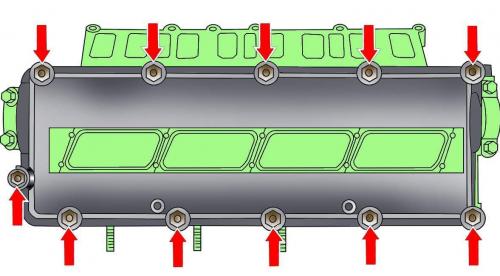
Pic. 3.4–46. Arrangement of bolts of fastening of a cover of a head of the block of cylinders
Unscrew the bolts and remove the cover of the left cylinder head (see fig. 3.4–46).
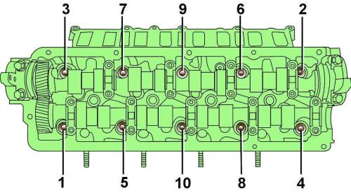
Pic. 3.4–57. Arrangement and sequence of an inhaling of bolts of fastening of a head of the block of cylinders
Unscrew the bolts and remove the left cylinder head (pic. 3.4–57).
Visitor comments