
Withdrawal
Remove the front cross member.
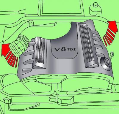
Pic. 3.4–19. Removing the engine cover
Pull the sides up to remove the engine cover (see fig. 3.4–19).
Loosen the screws and remove the protective cover located behind the air filter.
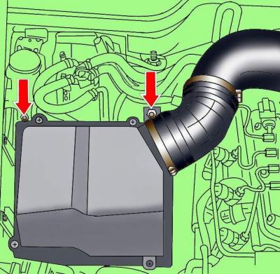
Pic. 3.4–1. Clamp location (1) fixing the air pipe and air filter fixing screws
Loosen the clamps and remove the air pipe connecting the air filter and the air pipe (see fig. 3.4–1).
Loosen the air filter housing screws.
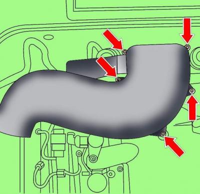
Pic. 3.4–2. Location of air pipe fixing screws
Loosen the screws and remove the air pipe (see fig. 3.4–2).
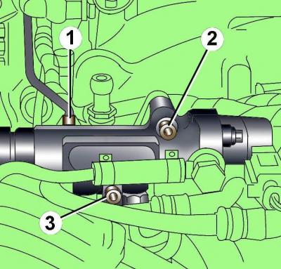
Pic. 3.4–48. Union nut location (1) and bolts (2, 3) fuel injection unit
Unscrew the end connection nut 1 (pic. 3.4–48).
Unscrew bolts 2 and 3, but do not completely remove the injection unit.
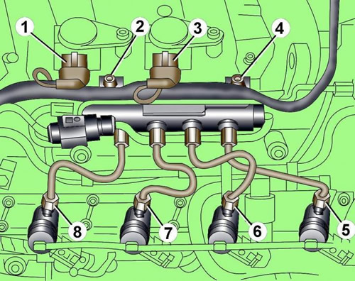
Pic. 3.4–49. Location of electrical connectors, bolts and connecting nuts for fastening fuel lines to the injection control unit (rail element): 1, 3 - electrical connectors; 2, 4 - bolts; 5, 6, 7, 8 - connecting nuts
Disconnect electrical connectors 1 and 3 (pic. 3.4–49), unscrew the connecting nuts 5–8 fastening pipelines and bolts 2 and 4 fastening the fuel injection control unit (Rail element).
Disconnect the electrical connectors from the glow plugs.
Remove the injection control unit (Rail element) from the intake manifold.
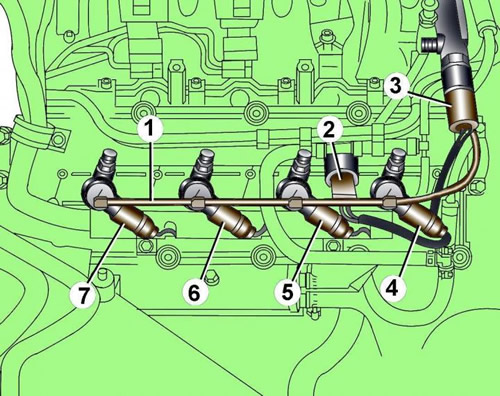
Pic. 3.4–50. Fuel return line location (1) and electrical connectors (2–7).
Disconnect electrical connectors 2-7 (pic. 3.4–50).
Unscrew the wire clamp and move the wires to the side (see fig. 3.4–50).
Release the fuel return line 1 from the clips and remove it from the fuel injectors.
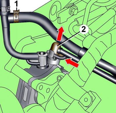
Pic. 3.4–51. Mounting clamp location (1) fuel hose to T-piece and fuel line mounting (2) to the fuel supply pump
Loosen clamp 1 and remove the fuel hose from the T-piece (pic. 3.4–51).
Remove the spring clip and disconnect the fuel line from the supply fuel pump (see fig. 3.4–51).
Disconnect the fuel lines near the right cylinder head cover.
Unscrew the oil filler cap.
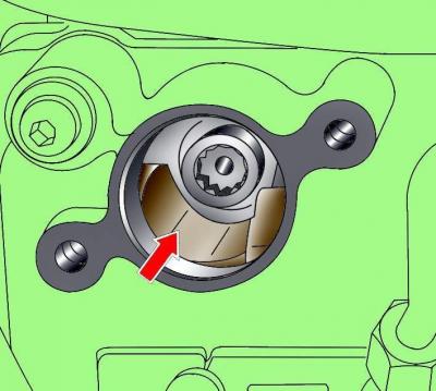
Pic. 3.4–43. The location of the notch in the oil filler hole
At the crankshaft pulley bolt, turn the shaft until a notch is visible in the oil filler hole (see fig. 3.4–43).
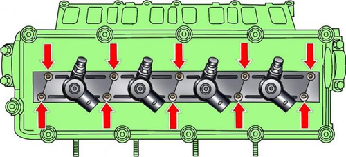
Pic. 3.4–44. Arrangement of bolts of fastening of casings of fuel atomizers
Unscrew the bolts securing the injector shrouds, pull the shrouds up and turn them 90°counterclockwise (see fig. 3.4–44).
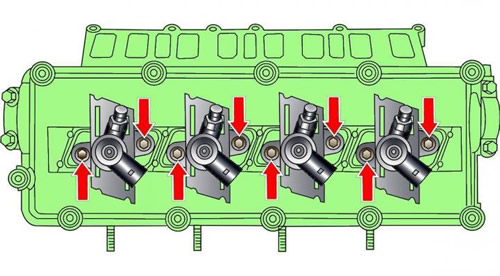
Pic. 3.4–45. Location of fuel injector mounting bolts
Unscrew the exposed injector mounting bolts (see fig. 3.4–45).
Pull up and remove the injectors of cylinders 1 and 3. When removing the injectors, you can use the lever.
Turn the crankshaft clockwise 180°and remove the injectors for cylinders 2 and 4.
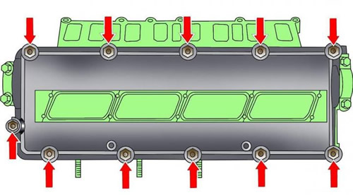
Pic. 3.4–46. Arrangement of bolts of fastening of a cover of a head of the block of cylinders
Unscrew the bolts and remove the right cylinder head cover (see fig. 3.4–46).
Installation
Installation is carried out in the reverse order of removal, taking into account the following.
Replace O-rings on fuel return pipes.
If necessary, replace the cylinder head cover gasket.
Install the sealing ring.
Degrease the surface to install the cylinder head cover gasket.
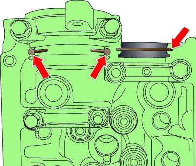
Pic. 3.4–47. Places for applying sealant before installing the left cylinder head cover
Apply a thin, continuous layer of sealant to the semi-circular surface (see fig. 3.4–47) at the end of the cylinder head.
Apply a 3 mm diameter layer of sealant in 5 mm projection lengths to the outer camshaft covers (see fig. 3.4–47).
Tighten nuts of fastening of a cover of a head of the block of cylinders gradually crosswise.
Install the front cross member.
Pour coolant into the cooling system.
Visitor comments