Table of contents: Removal ↓ Installation ↓
Removal
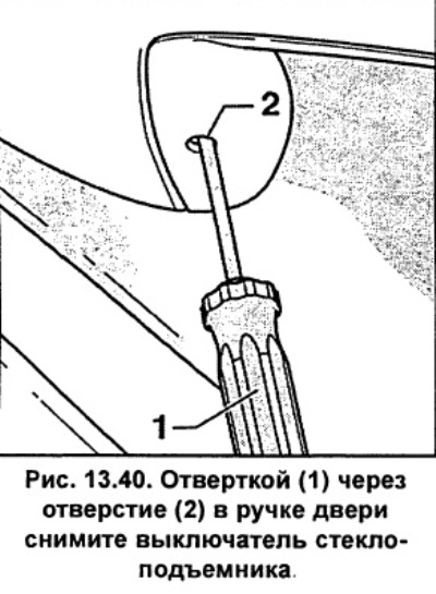
Remove the window switch. Insert a thin screwdriver 1 (fig. 12.40) at the bottom into the hole 2 of the door handle. On the passenger door next to the driver/rear door, hold the screwdriver horizontally, pressing the screwdriver handle against the door trim.
Move the screwdriver 3 (fig. 12.41) up to the stop. The screwdriver blade should be between the door handle and the locking lug 2 (fig. 12.41) switch.
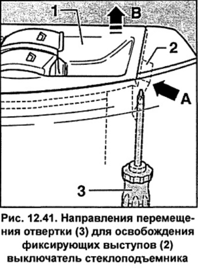
Press the locking tab 2 with a screwdriver (fig. 12.41) in the direction of arrow A. In this position, push the switch up, arrow B (fig. 12.41) and pull it out of the door handle.
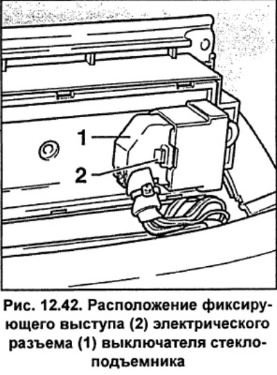
Press the locking tab 2 with a thin screwdriver (fig. 12.42) and disconnect electrical connector 2 from the window switch.
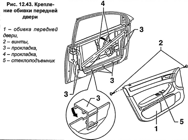
Remove two screws 2 (fig. 12.43) from door trim 1.
Lift the front door trim up 20 cm and remove it from the door.
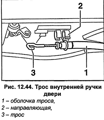
Pull out the cable sheath 1 (fig. 12.44) for the inner door handle from the guide 2 and remove the cable tip from the handle.
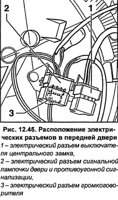
Remove and disconnect the electrical connectors on the back of the trim.
Installation
Check if rubber gaskets 3 and 4 are inserted (fig. 12.43) for fixing protrusions.
Check whether the absorbing molding element fits tightly against the door trim; if necessary, insert it into the guides.
Hang the door trim. Connect the electrical connectors and insert them into the holders until they click. Route the wire for the window switch through the hole in the door trim and insert the wire seal.
Hang the end of the interior door handle cable so that the hook points upward. Insert the cable sheath into the guides (fig. 12.44).
Push the door push button guide out of the trim. If the guide does not pop out, tape a thin wire to the top of the release button and feed the wire into the hole in the door trim. When installing the door trim, use the wire to guide the release button into the door button hole.
With the help of an assistant, insert the door trim into the holes in the door.
Press the door trim and slide it down until you hear clicks. While doing this, press in the middle of the clamp area 4 (fig. 12.43).
Connect the electrical connector to the window switch and snap it into place.
Place the bottom of the window switch into the socket, press down and snap it into place.
Tighten two screws 2 (fig. 12.43) door trim fastenings.
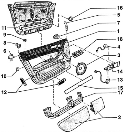
Fig. 12.39. Front door trim
1 - door trim,
2 - fold-down pockets,
3 - loudspeakers,
4 - high-frequency speakers,
5 - internal transition element,
6 - external transition element,
7 - internal insert,
8 - external insert,
9 - door button guide,
10 - pads for fixing protrusions,
11 - absorbing and sealing molding element,
12- door signal light,
13 - central lock switch,
14 - inner door handle,
15 - plug,
16 - foam part for sealing,
17 - console for fold-down pockets,
18 - window lift switch.