



Table of contents: Explanatory table for illustrations… ↓ Explanatory table for illustration… ↓ Explanatory table for illustration… ↓ Explanatory table for illustration… ↓
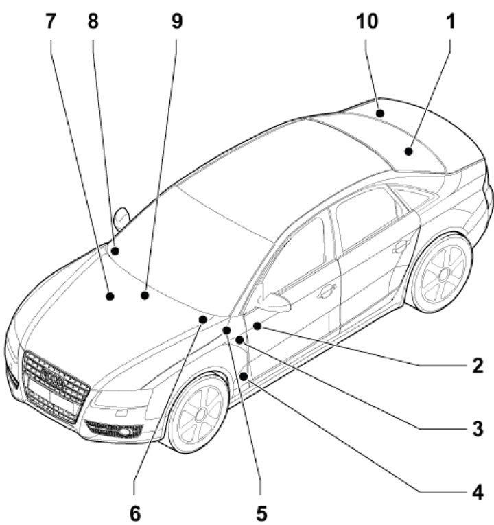
13.1. Location of relay and fuse mounting blocks 1. Fuse holder A "SA" (see illustration 13.2), second battery fuse (near the second battery) and battery cut-off fuse (near the second battery); 2. Fuse holder C "SC" (see illustrations 13.3 a-b); 3. Relay and fuse holder with on-board power supply control unit (see illustration 13.4); 4. 6-pin connector station at the bottom of the left A-pillar, behind the side trim (see illustration 13.5); 5. 3-pin relay and fuse holder for diesel models (see illustration 13.6); 6. Fuse holder B "SB" (see illustration 13.7); 7. 6-pin junction station at the bottom of the right A-pillar, behind the side trim (see illustration 13.8); 8.Fuse holder D "SD" (see illustration 13.9); 9. Twisting 2 (TV22) wires of terminal 30 and terminal U6 of engine start from auxiliary battery (see illustration 13.10); 10. Fuse holder F "SF" (see illustration 13.11)
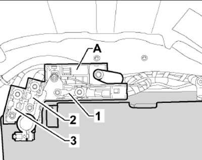
13.2. Fuse holder A "SA" (on the positive battery terminal, in the luggage compartment) A - Igniter (N₂53) emergency battery disconnection; 1. Fuse (SA1) for on-board power supply and power supply for engine components, 110 A, terminal 30; 2. Fuse (SA2) for on-board power supply and engine component power supply, 110 A, terminal 30; 3. Fuse (SA3), terminal 30: training vehicle - 40 A, rental vehicle - 50 A, executive vehicle - 110 A; on RHD models - fuse 1-3 of the ABS control unit (80 A)
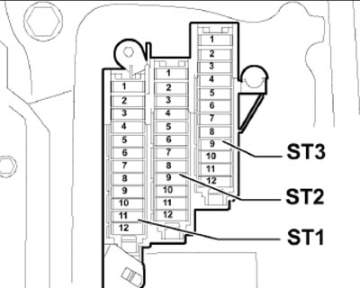
13.3a. Fuse holder C "SC" (behind the left instrument panel cover), models up to and including 2009
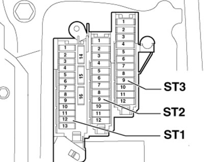
13.3b. Fuse holder C "SC" (behind the left instrument panel cover), models from 2010 inclusive
- ST1 Fuse Holder No.1 (Black), Terminal 15
- ST2 Fuse Holder No.2 (brown)
- ST3 Fuse Holder #3 (Red)
Explanatory table for illustrations 13.3a-b
| Number in the holder | Designation on diagrams | Current, A | Chain | Terminal |
| Fuses in holder ST1 | ||||
| 1 | SC1 | 5 | Active Steering Control Unit (J792) | 15 |
| 2 | SC2 | 5 | Clutch Pedal Sensor (F36), Clutch Pedal Sensor for Engine Start (F194) and Clutch Pedal Position Sensor (G476); not used on models since 2010 | 15 |
| 3 | SC3 | 5 | Universal remote control (E284) and its control unit (J530) | 15 |
| 4 | SC4 | 10 | Lane Departure Warning Control Unit (J759) | 15 |
| 5 | SC5 | 5 | Air Quality Sensor (G238) | 15 |
| 6 | SC6 | 5 | Headlamp range control (E102), headlamp range control unit (J431), right headlamp power output module (J668), headlamp turning and range control unit (J745), headlamp range control motors (V48/V49) | 15 |
| 7 | SC7 | 5 | Left Headlight Power Output Module (J667) | 15 |
| 8 | SC8 | 5 | On-board power supply control unit (J519) | 15 |
| 9 | SC9 | 5 | On models before 2009 - interior rearview mirror with automatic dimming (Y7); on models from 2010 - ACC control unit (J428) | 15 |
| 10 | SC10 | 5 | On models up to 2009 - selector lever sensor control unit (J587) and selector lever lock solenoid valve (N110); on 2010 and later models - see SC2 fuse circuit above | 15 |
| 11 | SC11 | 5 | Heating of left/right windshield washer nozzle (Z20/ Z21) | 15 |
| 12 | SC12 | 5 | Coolant temperature and pressure sensor (G395) | 15 |
| 13 | SC13 | 5 | T18a connector | 15 |
| 14 | SC14 | 5 | Hazard warning switch (E229), SRS control unit (J234), seat occupied detection unit (J706), hazard warning indicator (HMI) | 15 |
| 15 | SC15 | 25 | ABS control unit (J104), fuse holder "ST2" in block "SC", fuse holder "ST1" in block "SD" and fuse holder "ST4" in block "SF" | 15 |
| 16 | SC16 | 40 | Starter relay "J53", starter relay #2 (J695), fuse holder "ST1" with fuse "SB3" and fuse holder "ST1" with fuse "SB12" | 15 |
| Fuses in ST2 holder | ||||
| 1 | SC1 | 5 | On models up to 2009 - Circulation pump relay (J160) for 6-cylinder petrol models; on models from 2010 - interior rearview mirror with automatic dimming (Y7) | 87 |
| 2 | SC2 | 5 | Clutch Pedal Position Sensor (G476); On models before 2009 - additionally clutch pedal switch (F36), clutch pedal switch for starting the engine (F194) | 87 |
| 3 | SC3 | 20 | Fuel system filling pump (G6) for diesel models | 87 |
| 25 | Fuel pump control unit (J538) petrol models | |||
| 4 | SC4 | Before 2009 - 5A, since 2010 - 10 A | Circulation pump relay (J160) 6-cylinder petrol models; on models from 2010 - additional additive dosing control unit (J880) | 15 |
| 5 | SC5 | 30 | On-board power supply control unit (J519) | 30 |
| 6 | SC6 | 10 | ABS Control Unit (J104) LHD Models | 30 |
| 7 | SC7 | 25 | Horn relay (J413) | 30 |
| 8 | SC8 | 30 | Front/rear left door control unit (J386/J388) | 30 |
| 9 | SC9 | 30 | Windscreen wiper motor control unit (J400) | 30 |
| 10 | SC10 | 25 | ABS Control Unit (J104) LHD Models | 30 |
| 11 | SC11 | 15 | Front/rear left door control unit (J386/J388) | 30 |
| 12 | SC12 | 5 | Rain and light sensor (G397) | 30 |
| Fuses in ST3 holder | ||||
| 1, 2 | SC1, SC2 | Not used | ||
| 3 | SC3 | 10 | Driver/Passenger Seat Lumbar Support Adjustment Switch (E176/E177) | 30 |
| 4 | SC4 | 35 | Active Steering Control Unit (J792) | 30 |
| 5 | SC5 | 5 | Antenna amplifier #3 (R112); on models since 2010 - not used | 30 |
| 6 | SC6 | 35 | On-board power supply control unit (J519) | 30 |
| 7 | SC7 | 20 | 30 | |
| 8 | SC8 | 30 | 30 | |
| 9 | SC9 | 20 | Sunroof Control Unit (J245); on models from 2010 - additional sunroof curtain control unit (J394) | 30 |
| 10 | SC10 | 30 | On-board power supply control unit (J519) | 30 |
| 11 | SC11 | 20 | Sunroof Blind Control Unit (J394) | 30 |
| 12 | SC12 | 5 | Siren (H12) and anti-theft alarm sensor (G578) | 30 |
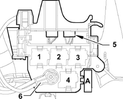
Relay and fuse holder with on-board power supply control unit (under the dashboard, on the left side) A - Fuse No.1 ABS control unit (S123), 40 A
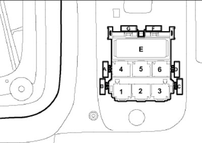
6-pin connector station at the bottom of the left A-pillar, behind the side trim A-E - Not used; F - Thermal fuse No.1 (S46) passenger seat adjustment, 15 A; G - Thermal fuse No.1 (S44) driver's seat adjustment, 15 A
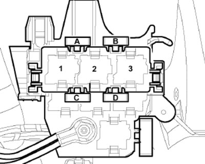
3-pin relay and fuse holder for diesel models (under the instrument panel, on the left side, on the relay and fuse holder with the on-board power supply control unit (BCM1) and screw connection) A, B - Not used; C - Fuse (S126) additional heater, 40 A; D - Fuse No.2 (S328) additional heater, 60 A
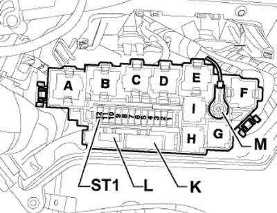
Fuse Holder B "SB" (in the electronics unit on the left side of the gutter) K - Fuse (S39) glow plug bus 4-cylinder diesel models, 60 A; K - Fuse (S39) glow plug bus 4-cylinder diesel models, 80 A; K - Fuse (S130) SAI pump 6-cylinder petrol models, 50 A; L - Not used; ST1 - Fuse Holder No.1
Explanatory table for illustration 13.7
| Number in the holder | Designation on diagrams | Current, A | Chain | Terminal |
| 1 | SB1 | 15 | AT control unit (J217) and DSG mechatronics unit (J743) | 30 |
| 2 | SB2 | 5 | Engine Oil Pressure and Temperature Sensor (G266) | 87 |
| 3 | SB3 | 5 | ECM (J623) and MAF sensor (G70)1,2 | 15 |
| 4 | SB4 | 5 | ECM (J623) | 30 |
| 5 | SB5 | 10², 153,4,6,7, 20¹ | MAF sensor (G70), pre-glow control unit (J179)8,7, SAI pump relay (J299)4, throttle valve module (J338)7, low/high heat output relay (J359/J360)6,7, electromagnetic boost pressure control valve (N75)6, heating element of the crankcase ventilation hose (N79)6, solenoid valve No.1 EVAP (N80)4, SAI valve (N112)4, solenoid valve left/right electrohydraulic engine mount (N144/N145)6/6,7, intake manifold geometry change valve (N156)4, air cleaner bypass valve (N₂75)67, fuel pressure regulating valve (N₂76)1,2, fuel metering valve (N₂90)4, valve No.2 SAI (N320)4, EGR radiator switching valve (N345)6,7, oil pressure regulating valve (N428)4,7, fuel supply system leak diagnostic pump (V144)4 | 87 |
| 6 | SB6 | 15 | ECM | 87 |
| 7 | SB7 | 101,3,6,7, 152,4 | Activator 1-8 camshaft adjustment (F366-F374)24, activator 9-12 camshaft adjustment (F3375-F377)4, continuous coolant circulation relay (J151)1,2, additional coolant pump relay (J496)4, electromagnetic boost pressure control valve (N75)1,2, solenoid valve No.1 EVAP (N80)1,2, solenoid valve of the left electrohydraulic engine support (N144)1,2, intake camshaft adjustment valve No.1 (N₂05)1,2,4, intake camshaft adjustment valve No.2 (N₂08)4, charge air circulation valve (N₂49)1,2, fuel pressure regulating valve (N₂76)6,7, fuel metering valve (N₂90)6,7, intake manifold flap valve (N316)², exhaust camshaft adjustment valve No.1 (N318)4, valve No.2 for adjusting the exhaust shaft (N319)1,4, climate control system coolant cut-off valve (N422)1,2,4, oil pressure regulating valve (N428)1,2, fuel supply system leak diagnostic pump (V144)² | 87 |
| 8 | SB8 | 106,7, 201,4 | Ignition coil #1-#4 with output stage (N70,N127,N₂91,N₂92)1,2, climate control system coolant cut-off valve (N422)6, EGR radiator pump (V400)6,7 | 87 |
| 9 | SB9 | 153,4, 206,7 | Additional fuel pump relay (J832)6,7 | 87 |
| 10 | SB10 | 15 | Lambda probe heater (Z19)1,2,6,7, Lambda probe heater No.2 (Z28)¹, post-catalytic lambda probe heater No.1 (Z29)² | 87 |
| 11 | SB11 | 5 | Radiator Fan Control Unit #1/#2 (J293/J671)7 | 87 |
| 12 | SB12 | 5 | MAF sensor (G70)6,7, AT control unit (J217), DSG mechatronics unit (J743) | 15 |
- ¹ for petrol models 1.8 l
- ²for 2.0L petrol models
- ³ for 3.0L petrol models
- 4 for petrol models 3.2 l
- 6 for diesel models 2.0 l
- 7for diesel models 2.7 and 3.0 l
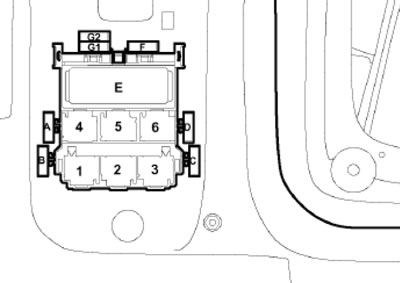
6-pin junction station at the bottom of the right A-pillar, behind the side trim, RHD models only A-E - Not used; F - Fuse No.1 ABS control unit (S123), 40 A; G1/G2 - Fuse No.3/No. 2 ABS control unit (S137/S124), 25/10 A
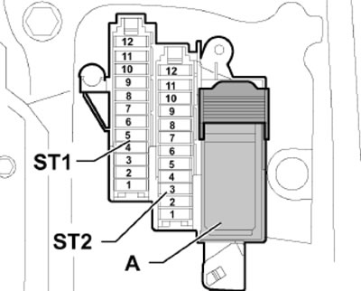
Fuse Holder D "SD" (under the instrument panel trim, on the right side) ST 1 Fuse Holder No.1 (Black) ST2 Fuse Holder No.2 (brown) A 46-pin connector (T46s) in the instrument panel, black, CAN disconnect
Explanatory table for illustration 13.9
| Number in the holder | Designation on diagrams | Current, A | Chain | Terminal |
| Fuses in holder ST1 | ||||
| 1-4 | SD1-SD4 | Not used | ||
| 5 | SD5 | 5 | Steering column electronics control unit (J527) | 15 |
| 6 | SD6 | 5 | TCS/ESP button (E256) and parking assistance system switch (E266) | 15 |
| 7 | SD7 | 5 | Diagnostic connector (T16) | 15 |
| 8 | SD8 | 5 | Data bus diagnostic interface (J533) | 15 |
| 9 | SD9 | 5 | High Heat Output Relay (J360) | |
| 10-12 | SD10-SD12 | 5 | Not used | |
| Fuses in ST2 holder | ||||
| 1 | SD1 | 5 | CD changer (R41), DVD changer (R161), connection for external audio source (R199) | 30 |
| 2 | SD2 | 5 | Switch module for model "Charisma" (E592) | 30 |
| 3 | SD3 | 5 | On models with MMI (MOST bus): MMI display (J685) and information electronics control unit no. 1 (J794) | 30 |
| 20 | On models with CAN information bus: Audio unit (R) | 30 | ||
| 4 | SD4 | 5 | Light switch (E1) and control unit in instrument panel insert (J285) | 30 |
| 5 | SD5 | 5 | Control unit in instrument panel insert (J285) and data bus diagnostic interface (J533) | 30 |
| 6 | SD6 | 5 | Keyless entry switch (E415) | 30 |
| 7 | SD7 | 5 | Light switch (E1) | 30 |
| 8 | SD8 | 40 | Air conditioning fan control unit (J126) | 30 |
| 9 | SD9 | 5 | Electronic steering column lock control unit (J764) | 30 |
| 10 | SD10 | 10 | Climate control unit (J255) | 30 |
| 11 | SD11 | 10 | Diagnostic connector (T16) | 30 |
| 12 | SD12 | 5 | Steering column electronics control unit (J527) | 30 |
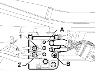
Twisting 2 (TV22) wires of terminal 30 and terminal U6 of engine start from auxiliary battery (in the center of the gutter) A - Twisting 2 wires of terminal 30 (TV22); B - Terminal for starting the engine from the auxiliary battery (U6); 1 - Fuse #1 "S204" (terminal 30): radiator fan control 400 W - 40 A, fan control¹ radiator 600W - 60A, Radiator Fan Control 600W - 60A; 2 - Fuse No.2 "S205" (terminal 30): fan control¹ radiator 400 W - 40 A; ¹ Fuses S204 (600W) and S205 (400W) are installed on models with 1000W radiator control
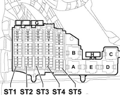
Fuse holder F "SF" behind right side trim of luggage compartment ST1 - Fuse Holder No.1 (Black); ST2 - Fuse Holder No.2 (Black); ST3 - Fuse Holder No.3 (brown); ST4 - Fuse Holder No.4 (Red); ST5 - Fuse Holder #5 (Black); H - Fuse (S41) rear window heating relay (J9), 40 A, terminal 30
Explanatory table for illustration 13.11
| Number in the holder | Designation on diagrams | Current, A | Chain | Terminal |
| Fuses in holder ST1 | ||||
| 1 | SF1 | 30 | Luggage Compartment Lid Control Module 2 (J756), only on models up to and including 2009 | 30 |
| 2 | SF2 | Not used | ||
| 3 | SF3 | 30 | Tailgate Control Module (J605), models up to and including 2009 only | 30 |
| 151,3, 252,3 | Signaling system control unit (J616) | |||
| 4 | SF4 | 5 | 2-pin blue-purple connectors (T2da/T2db), only on models up to and including 2009 | 87 |
| 15³ | Signaling system control unit (J616) | 30 | ||
| 5 | SF5 | 51,3 | Working block of special signals (E507) | 30 |
| 152,3 | Signaling system control unit (J616) | |||
| 6 | SF6 | 33 | Special signal operating unit (E507)1, signal system control unit (J616), tachograph control unit (J621)2, 3-pin connector (T3d), "black box" | 15 |
| 7 | SF7 | 203 | Special vehicle control unit (J608) | 30 |
| 8 | SF8 | 103 | "Black box" | 30 |
| 9 | SF9 | 103 | Socket No.4 12 Volt (U20) | 30 |
| 10, 11 | SF10, SF11 | 103 | 2-channel radio cut-off relay (J84) | 30 |
| 12 | SF12 | Not used | ||
- ¹ For doctor's car only (f4Z version)
- ² Only for the doctor's car (f4X version) or the fire brigade (f4Q version)
- ³ only models from 2010 onwards.
| Fuses in ST2 holder | ||||
| 1 | SF1 | 51, 302 | Tire inflation pressure monitoring system control unit (J502), luggage compartment lid control unit no. 2 (J756)2 | 30 |
| 2 | SF2 | 15 | Trailer Detection Control Unit (J345) | 30 |
| 3, 4 | SF3, SF4 | 20 | ||
| 5 | SF5 | 5 | Parking brake switch (E538)¹ or "AUTO HOLD" switch (E540)² | 30 |
| 6 | SF6 | 15 | Suspension Rigidity Control Unit (J250) | 30 |
| 7 | SF7 | 30 | Parking brake control unit (J540) | 30 |
| 8 | SF8 | 30 | Comfort control unit (J393) | 30 |
| 9 | SF9 | 35 | All-wheel drive control unit (J492) | 30 |
| 10 | SF10 | 30 | Comfort control unit (J393) | 30 |
| 11 | SF11 | 20 | Comfort control unit (J393) | 30 |
| 12 | SF12 | 5 | Vehicle Positioning System Interface Control Unit (J843) | 30 |
- ¹ Only models up to and including 2009
- ² Only models from 2010 onwards.
| Fuses in ST3 holder | ||||
| 1 | SF1 | 15¹, 30² | Inverter 230 Volt (U13)3 | 30 |
| 30 | Luggage compartment lid control unit (J605)4 | 30 | ||
| 2 | SF2 | 15 | Front right seat ventilation control unit (J799) | 30 |
| 3 | SF3 | 7.5³, 404 | Control unit for navigation system with CD drive (J401)³, audio unit (R), telephone transceiver unit (R36), television receiver (R78), mobile telephone antenna amplifier (R86), telephone bracket (R126), satellite/digital radio receiver (R146/R147)3, 18-pin black connector (T18a) | 30 |
| 4 | SF4 | 30³, 404 | Sound Processing Control Unit (J525)³ or Voltage Regulator (J532)4 | 30 |
| 5 | SF5 | 5³, 304 | MMI Display Control Unit (J523)³ or 230 Volt Inverter (U13)4 | 30 |
| 6 | SF6 | 30 | Additional heater control unit (J364) | 30 |
| 7 | SF7 | 30 | Parking brake control unit (J540) | 30 |
| 8 | SF8 | 30 | Heated left/right rear seat, with regulator (E128/E129) | 30 |
| 9 | SF9 | 30 | Front/rear right door control unit (J387/J389) | 30 |
| 10 | SF10 | 5 | Additional heater remote control receiver (R64) | 30 |
| 11 | SF11 | 15 | Front/rear right door control unit (J387/J389) | 30 |
| 12 | SF12 | 5³, 304 | Reversing camera control unit (J772)³ or additive dosing control unit (J880)4 | 30 |
- ¹ No longer in use, gradual modification
- ² Gradual modification
- ³ Only models up to and including 2009
- 4 Only models from 2010 onwards.
| Fuses in ST4 holder | ||||
| 1 | SF1 | 15 | Socket 12V No.2 (U18) | 87 |
| 2 | SF2 | 15 | 12V socket (U5), 230V inverter (U13)² | 87 |
| 3 | SF3 | 15 | Socket 12V No.3 (U19) | 87 |
| 4 | SF4 | 15 | Cigarette lighter (U1) | 87 |
| 5 | SF5 | 51 | Parallel Parking Assist Control Unit (J791)¹ | 15 |
| 6 | SF6 | 5 | 18-pin black connector (T18a)¹ | 15¹ |
| Preparation for entertainment system² in the driver/front passenger seat backrest | 87² | |||
| 7 | SF7 | 5¹, 7.5² | ACC Control Unit (J428)¹ or parallel parking assist control unit (J791)² | 15 |
| 8 | SF8 | 15 | Rear window wiper motor (V12) | 15 |
| 9 | SF9 | 5 | Parking brake switch (E538) | 15 |
| 10 | SF10 | 5 | Control unit #2 of the system "Lane assist" (J770) | 15 |
| 11 | SF11 | 5 | Rear left seat heating, with regulator (E128) | 15 |
| 12 | SF12 | 5 | Emergency signal switch (ES)¹, SRS control unit (J234)¹, Damper Control Unit (J250)², Trailer Detection Unit (J345)², All-Wheel Drive Control Unit (J492)², Voltage Stabilizer (J532)², Parking Brake Control Unit (J540)², Seat Occupied Detection Unit (J706)¹, K/L for disabling front passenger airbag (K145)¹ | 15 |
- ¹ Only models up to and including 2009
- ² Only models from 2010 onwards.
| Fuses in ST5 holder | ||||
| 1 | SF1 | Not used | ||
| 2 | SF2 | Not used | ||
| 3 | SF3 | 101,6, 152,4,5,6, 253,8 | Special vehicle control unit (J608)1,4,5,6, signal system control unit (J616)2,3,6 | 308 |
| 201,9, 302,9 | Sound Processing Control Unit (J525)³, Audio Unit (R)8 | 159 | ||
| 4 | SF4 | 152,3,8,105,8 | Signaling system control unit (J616)2,3, 2-channel radio (R8)5 | 308 |
| 7.59 | Information Electronics Control Unit No.1 (J794)9 | 159 | ||
| 5 | SF5 | 52,5,8 153,8 | Chip card reader (D8)5,8, working block of special signals (E507)2,3, signal system control unit (J616)3,8 | 30 |
| 75,9 | Control unit for navigation system with CD drive (J401)9, audio block (R)9, telephone transceiver unit (R36)9, television receiver (R78)9, mobile phone antenna amplifier (R86)9, telephone bracket (R126)9, 18-pin black connector (T18a)9 | |||
| 6 | SF6 | 108 | Chip card reader (D8)5,8, working block of special signals (E507)2,3, taximeter (G41)5,6, taxi alarm remote control unit (J601)5,6, control unit for special vehicle (J608)1,8, signal system control unit (J616)2,3,8 | 158 |
| 59 | Rear view camera control unit (J772)9 | 309 | ||
| 7 | SF7 | 55,8, 202,3,8 | Taxi alarm remote control unit (J601)5, control unit for special vehicle (J608)2,3 | 308 |
| 8 | SF8 | 108 | Tachograph control unit (J621)³, data transmission control unit (J753)5, "black box"2,3 | 308 |
| 9 | SF9 | 108 | Socket No.4 12 Volt (U20) | 308 |
| 10, 11 | SF10, SF11 | 108 | 2-channel radio cut-off relay (J84)2,3 | 308 |
| 12 | SF12 | Not used | 30 | |
- ¹ For training vehicles only (F5F)
- ² Only for special vehicles (F4J, F4Z)
- ³ For special vehicles only (F4G, F4Q, F4X)
- 4 For disabled vehicles only (F6M)
- 5 For rental cars only (F4E, F4F)
- 6 For models with sound system only "Basic" (8RE)/"Basic plus" (8RX)
- 7 Only except models with sound system "Basic" (8RE)/"Basic plus" (8RX)
- 8 Only models up to and including 2009
- 9 Only models from 2010 onwards.
(This article was copied from an online resource: «AUDImanual»)