
Repair Chevrolet Repair Toyota Repair Honda Repair AvtoVAZ Repair Mercedes-Benz Repair BMW Repair Opel
Home  |  Contacts  |  Sitemap  |    
English Русский
Български
Беларускі
Український
Српски
Hrvatski
Română
Polski
Slovenský
Magyar
AudiManual.ru


  • AUDI 80
  • AUDI 100
  • AUDI A3
  • AUDI A4
  • AUDI A6
  • AUDI A8
  • AUDI Q
  • OTHER
  • ARTICLES
B8 (2007-2015) B7 (2004-2008) B6 (2000-2006) B6 (2000-2006, petrol) B5 (1994-2001) B5 (1994-2001, petrol)

Engine management system 1.8 TFSI (CABA/CABB, CDHA/CDHB) (Audi A4 B7)

  • Home
  • Audi A4
  • B7 (2004-2008)
  • Electrical equipment
  • Electrical diagrams (since 2007)
  • Engine management system 1.8 TFSI (CABA/CABB, CDHA/CDHB)
            0
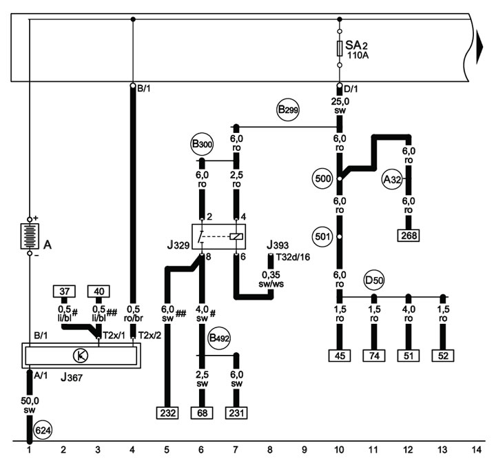
1-1 Battery, power relay terminals 15

1-1 Battery, power relay terminals 15
# Up to 2009 issue. (inclusive)
# # Since 2010.
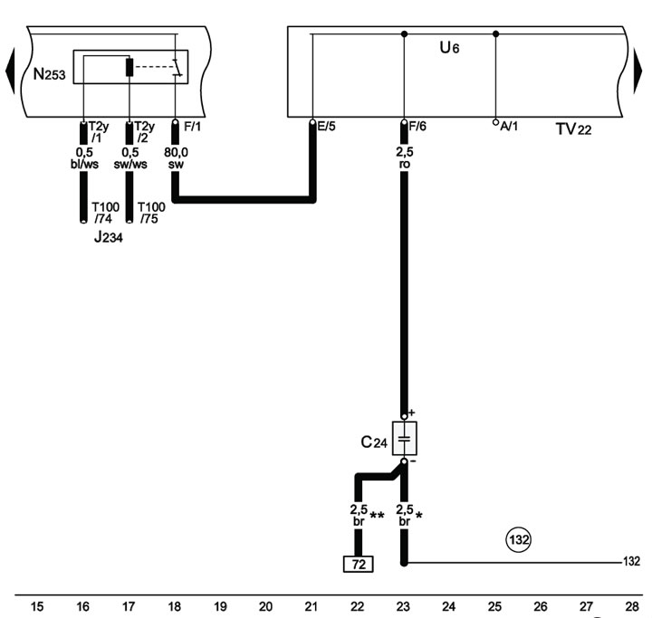

1-2 Suppression filter, battery emergency shutdown squib, auxiliary battery start terminal

1-2 Suppression filter, battery emergency shutdown squib, auxiliary battery start terminal
*No longer in use, gradual change
** Gradual change
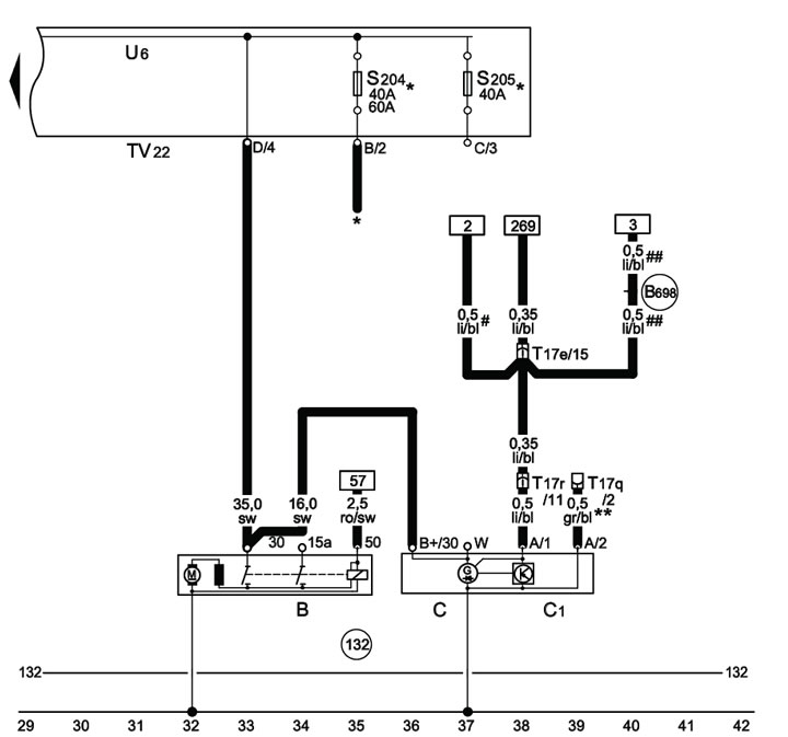

1-3 Starter, generator, auxiliary battery start terminal

1-3 Starter, generator, auxiliary battery start terminal
* see radiator fan diagram
**No longer in use, gradual change
# up to 2009. (inclusive);
# # since 2010
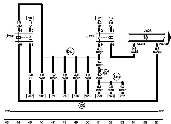


1-4 ECM Power Relay, Engine Component Power Relay
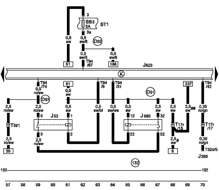
1-4 ECM Power Relay, Engine Component Power Relay


1-5 Starter relay

1-5 Starter relay
# Up to 2009 issue. (inclusive)
# # Since 2010.
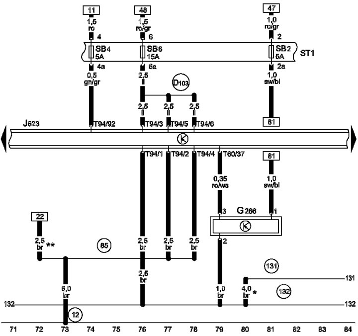

1-6 Terminal 30 power supply for ECM, engine oil level and temperature sensor

1-6 Terminal 30 power supply for ECM, engine oil level and temperature sensor
* Section 2.5, gradual change
** Gradual change
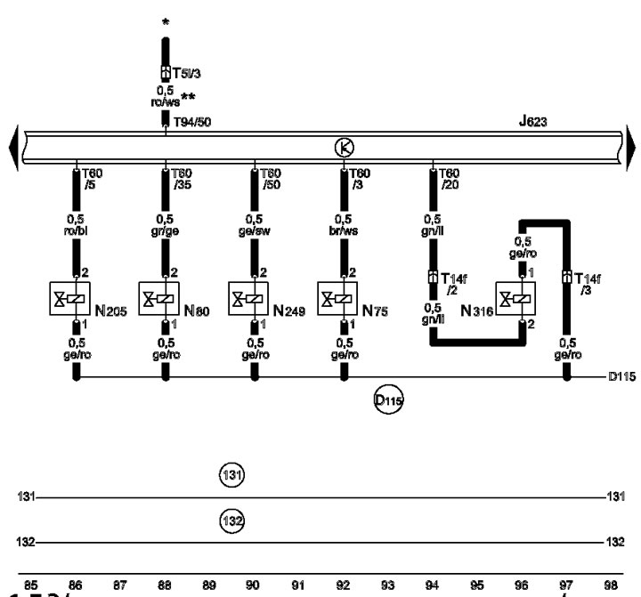

1-7 Solenoid valve for regulating the boost pressure, Solenoid valve #1 EVAP, Solenoid valve #1 for…

1-7 Solenoid valve for regulating the boost pressure, Solenoid valve #1 EVAP, Solenoid valve #1 for adjusting the intake camshaft, Valve of recirculation of the boost air. Valve of the intake manifold flap
*See radiator fan diagram;
** section 0.35, gradual change
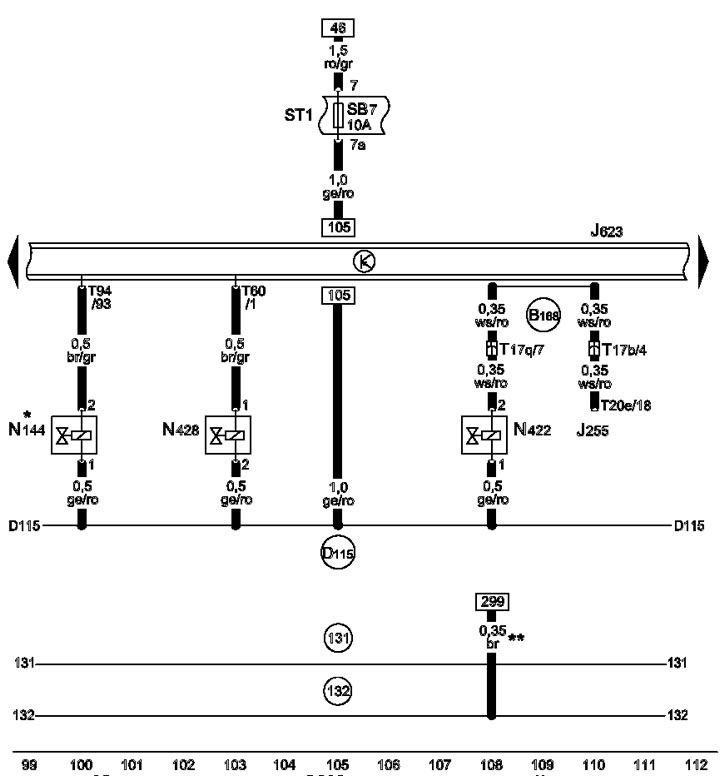


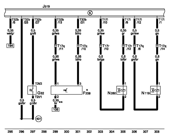
1-8 Air conditioning system coolant cut-off valve, oil pressure control valve

1-8 Air conditioning system coolant cut-off valve, oil pressure control valve
* for models with solenoid valve of the left electro-hydraulic engine support
** section 0.5, gradual change


1-9 Lambda probes, continuous coolant circulation relay

1-9 Lambda probes, continuous coolant circulation relay
* for models with continuous circulation coolant pump
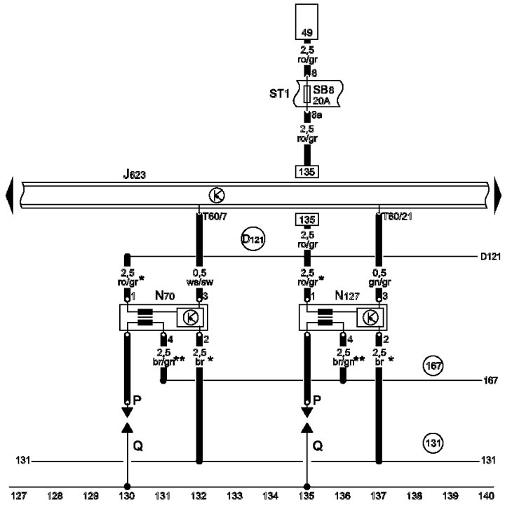

1-10 Ignition coils 1-2

1-10 Ignition coils 1-2
* section 1.5, gradual change
** section 0.5, gradual change
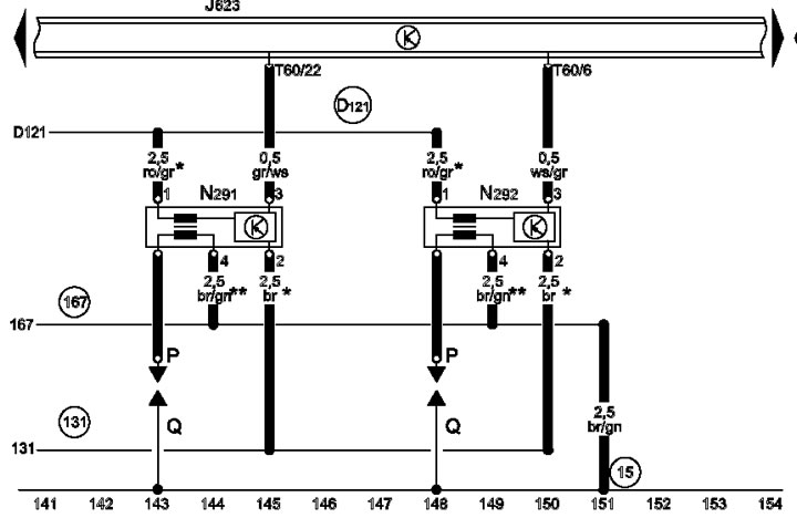


1-11 Ignition coils 3-4

1-11 Ignition coils 3-4
* section 1.5, gradual change
** section 0.5, gradual change
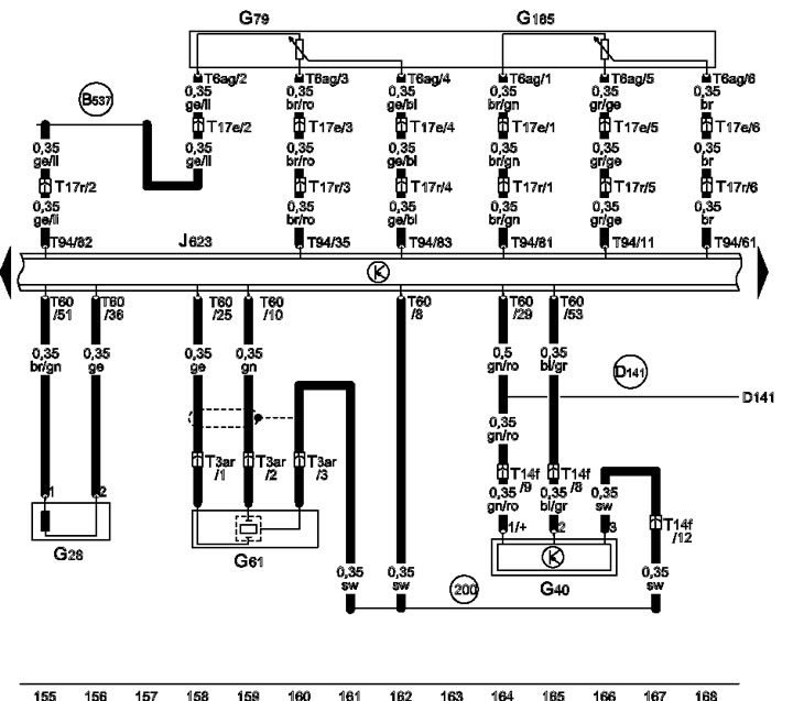

1-12 Sensors SKR, SMR, KS No.1, gas pedal position sensor
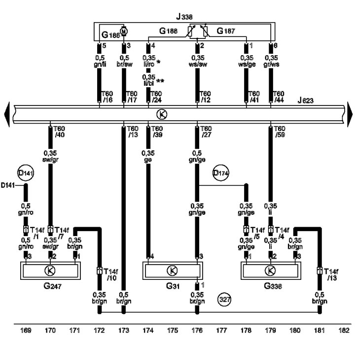
1-12 Sensors SKR, SMR, KS No.1, gas pedal position sensor


1-13 Boost Pressure Sensor, Intake Manifold Flapper Position Sensor, Throttle Module, Fuel Pressure…

1-13 Boost Pressure Sensor, Intake Manifold Flapper Position Sensor, Throttle Module, Fuel Pressure Sensor
*No longer in use, gradual change
** Gradual change
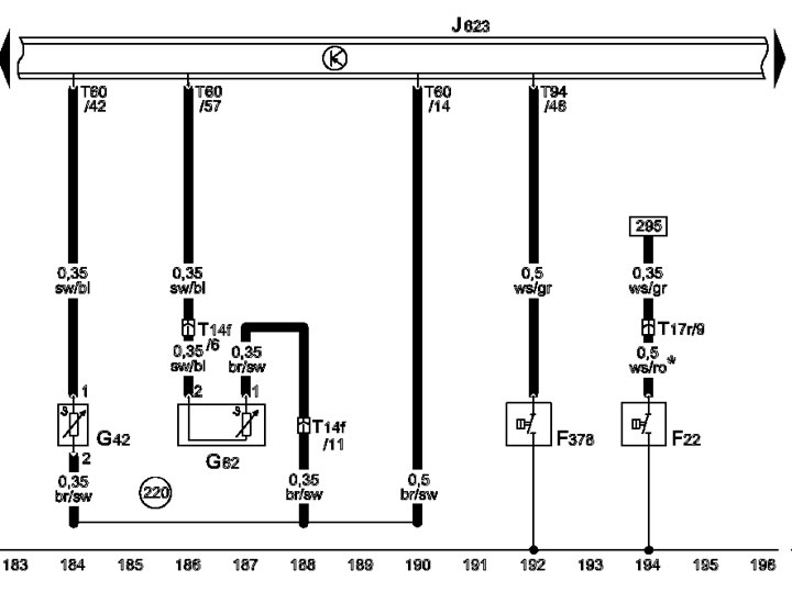

1-14 Engine oil pressure sensor, temperature sensor

1-14 Engine oil pressure sensor, temperature sensor
* Wire color changed to white/gray, gradual change
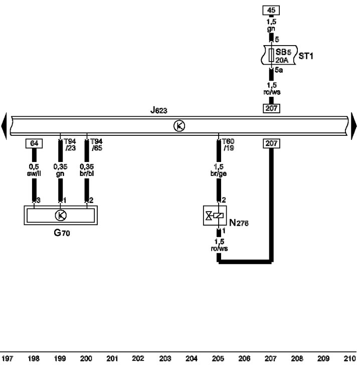


1-15 MAF sensor, fuel pressure control valve
1-15 MAF sensor, fuel pressure control valve


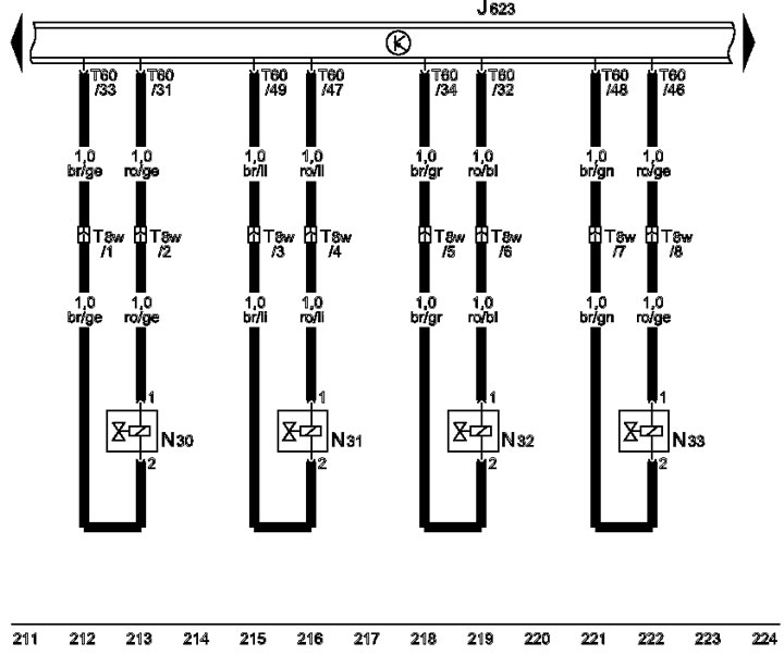
1-16 Injectors
1-16 Injectors


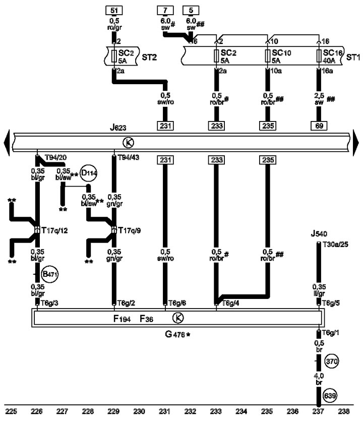
1-17 Clutch position sensor

1-17 Clutch position sensor
* Models with manual transmission;
** Models with AT
# since 2009. (inclusive);
# # since 2010.
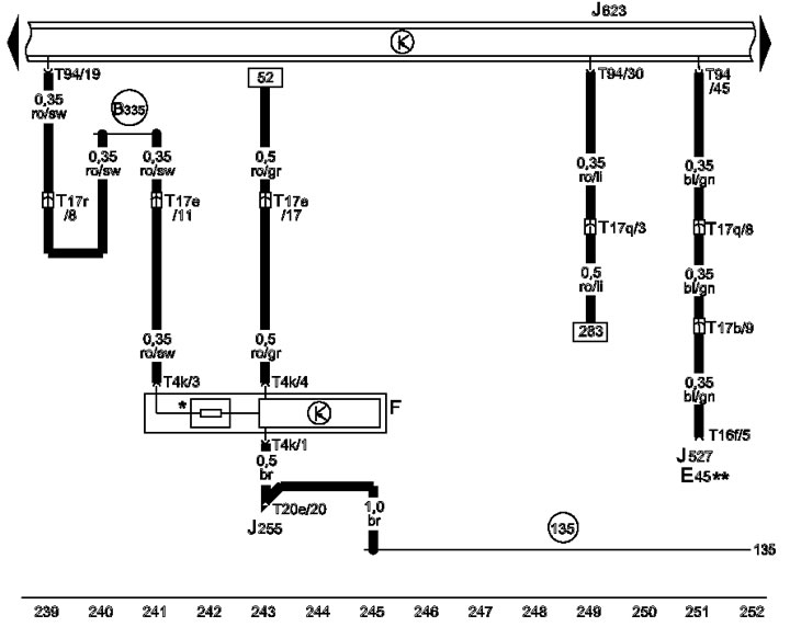

1-18 D/W brake lights

1-18 D/W brake lights
* Brake light coil
** For models with tempostat
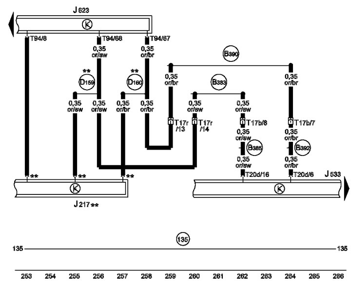


1-19 CAN bus powertrain, AT control unit

1-19 CAN bus powertrain, AT control unit
** For models with AT
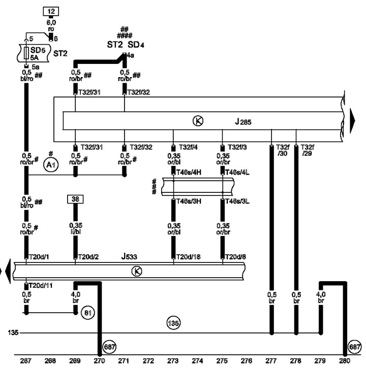

1-20 Control unit in the instrument panel insert

1-20 Control unit in the instrument panel insert
# Up to 2009 issue. (inclusive);
# # Since 2010.
# # # Brown Insert Bridge
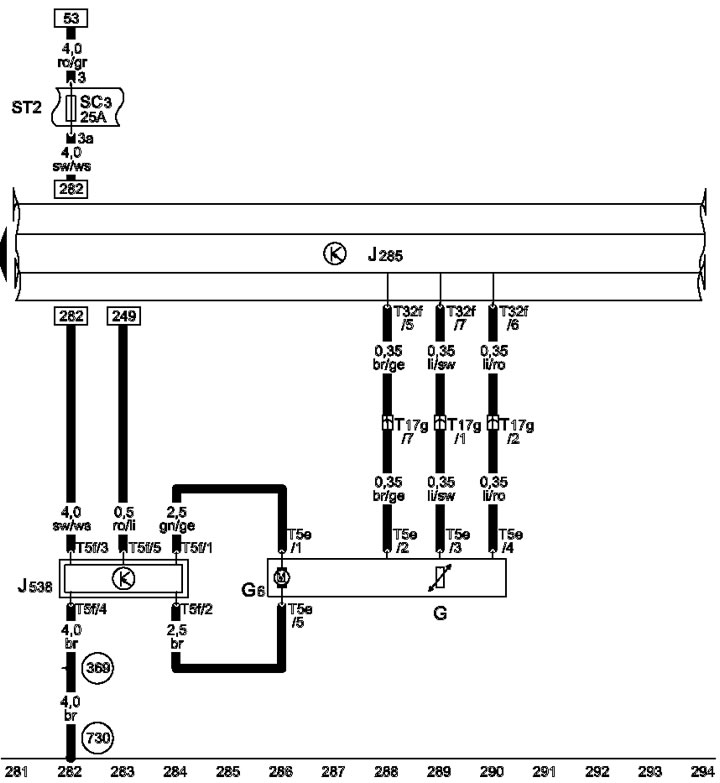

1-21 Control unit in instrument panel insert, fuel gauge, fuel supply system filling pump
1-21 Control unit in instrument panel insert, fuel gauge, fuel supply system filling pump


1-22 Low Coolant Sensor

1-22 Low Coolant Sensor
* For models with manual transmission
** section 0.5, gradual change


(Text provided by the online resource: «AUDIMANUAL»)
The article was checked by auto expert Timur Bazhenov
This article is available at russian, bulgarian, belarusian, ukrainian, serbian, croatian, romanian, polish, slovak, hungarian

Share information:
Previous articles
Audi A4 B7: Electrical diagrams (since 2007)
Next articles

Designations on diagrams
Location of relays and fuses
Color designations for wire insulation and fuses
Radiator fan (400 W), for petrol models, from September 2007
6-speed AT (0B6), since September 2007
CVT (0AW), since September 2007
DSG (0B5), since September 2008


Similar articles on other Audi car models:
Electrical diagram of the control unit of the fuel system of the… Audi 80 B4 (1991-1996)
Lubrication system of a 6-cylinder gasoline engine Audi 100 C4 (1990-1994)
Engine Management System 1.6L Audi A3 Type 8L (1996-2003)
Engine management system Monomotronic Audi A6 C4 (1994-1997)
Operation of the engine management system Audi A8 D2 (1994-2002)
Operating principles of the engine management system Audi Q7 Typ 4L (2005-2015, diesel)
Pressure reducing valve of the engine crankcase ventilation… Audi A2 (1999-2005)
Link to this page in different formats


Visitor comments

No comments yet


How much will 32 + 31 =


A4(B8, 2007-2015) 
  • General information
  • Operating instructions
  • Power unit
  • Petrol engines 1.8 l
  • Petrol engines 1.8/2.0 l
  • Petrol engines 3.0 l
  • Petrol engines 3.2 l
  • Fuel system (petrol)
  • Diesel engines 2.0 l (CA*)
  • Diesel engines 2.0 l (CJCB)
  • Diesel engines 2.7/3.0 l
  • Diesel engines 3.0 l
  • Fuel system (diesel)
  • Transmission
  • Manual gearbox 0B1
  • Manual gearbox 0B2
  • Manual gearbox 0B3
  • Manual gearbox 0B4
  • Automatic transmission 0B5
  • Automatic transmission 0B6
  • Automatic transmission 0AW
  • All-wheel drive system
  • Chassis
  • Front suspension
  • Rear suspension
  • Brake system
  • Steering system
  • Body
  • Exterior
  • Interior
  • Seats
  • Doors, locks and windows
  • Security system
  • Heating and air conditioning
  • Electrical equipment
  • Audio system
  • Power devices
  • Equipment and devices
  • Lighting and lamps
  • Electrical circuits
 
A4(B7, 2004-2008) 
  • General information
  • Introduction to manual
  • Troubleshooting
  • Operating instructions
  • Maintenance
  • Power unit
  • Petrol engines 2.0 (ALT)
  • Petrol engines 2.0 (TFSI)
  • Petrol engines 1.8 (MPI)
  • Diesel engines
  • Cooling system
  • Air conditioner
  • Fuel and exhaust system
  • Ignition system
  • Starting and charging
  • Transmission
  • Clutch
  • Manual gearbox
  • Automatic gearbox
  • Drive shafts
  • Chassis
  • Brake system
  • Front suspension
  • Rear suspension
  • Steering
  • Body
  • Exterior
  • Interior
  • Electrical equipment
  • Equipment and devices
  • Lighting and signaling
  • Windscreen wipers and washers
  • Electrical diagrams
  • Electrical diagrams (since 2007)
 
A4(B6, 2000-2006) 
  • General information
  • Vehicle Description
  • User manual
  • Maintenance
  • Power unit
  • Gasoline engine
  • Diesel engine
  • Lubrication system
  • Cooling system
  • Supply system
  • Injection system
  • Exhaust system
  • Ignition and control
  • Transmission
  • Gear box
  • Clutch and drive shafts
  • Chassis
  • Brake system
  • Car suspension
  • Steering
  • Body
  • Heating and ventilation
  • Exterior (external elements)
  • Interior (internal elements)
  • Electrical equipment
  • Power devices
  • Lighting and appliances
  • Electrical circuits
 
A4(B6, 2000-2006, petrol) 
  • General information
  • Introduction to the guide
  • Car care
  • Power unit
  • Engine repair
  • Lubrication system
  • Cooling system
  • Injection and control system
  • Ignition system
  • Power and exhaust system
  • Transmission
  • Clutch and drive shafts
  • Car gearbox
  • Chassis
  • Suspension and wheels
  • Steering
  • Brake system
  • Body
  • Interior
  • Exterior
  • Electrical equipment
  • Equipment and devices
  • Lighting and signaling
  • Power devices
  • Electrical circuits
 
A4(B5, 1994-2001) 
  • General information
  • Introduction to the guide
  • Car care
  • Maintenance (gasoline)
  • Maintenance (diesel)
  • Power unit
  • Gasoline engines
  • Diesel engines
  • Engine overhaul
  • Cooling system
  • Fuel injection (gasoline)
  • Fuel system (diesel)
  • Exhaust system
  • Ignition system
  • Transmission
  • Clutch
  • Mechanical gearbox
  • Automatic gearbox
  • Drive shafts
  • Chassis
  • Brake system
  • Car suspension
  • Steering
  • Body
  • Exterior
  • Interior
  • Doors, locks and windows
  • Heating and ventilation
  • Electrical equipment
  • Power devices
  • Equipment and devices
  • Electrical circuits
 
A4(B5, 1994-2001, petrol) 
  • General information
  • Vehicle description
  • Maintenance
  • Power unit
  • Engine repair
  • Turbocharging
  • Exhaust system
  • Cooling system
  • Ignition system
  • Fuel system
  • Motronic injection system
  • MPI and MPFI injection system
  • Transmission
  • Clutch
  • Gearbox and shafts
  • Chassis
  • Steering
  • Car suspension
  • Brake system
  • Wheels and tires
  • Body
  • Heating and ventilation
  • Body parts
  • Electrical equipment
  • Fuses and relays
  • Power devices
  • Lighting and lamps
  • Tools and devices
  • Electrical circuits
 
AudiManual.ru © 2017-2026 · Mobile version · Feedback · Sitemap: EN BG BY UA RS HR RO PL SK HU · Site search · News and articles
80 B2 · 80 B3 petrol · 80 B3 · 80 B4 · 100 C3 diesel · 100 C3 petrol · 100 C3 · 100 C4 petrol · 100 C4 · A3 Type 8L · A4 B5 petrol · A4 B5 · A4 B6 petrol · A4 B6 · A4 B7 · A4 B8 · A6 C4 · A6 C5 · A6 C5 Allroad · A8 D2 · Q5 Type 8R · Q7 Typ 4L · Audi A2 ·
This site uses cookies 🍪. Click the button to accept this fact.