
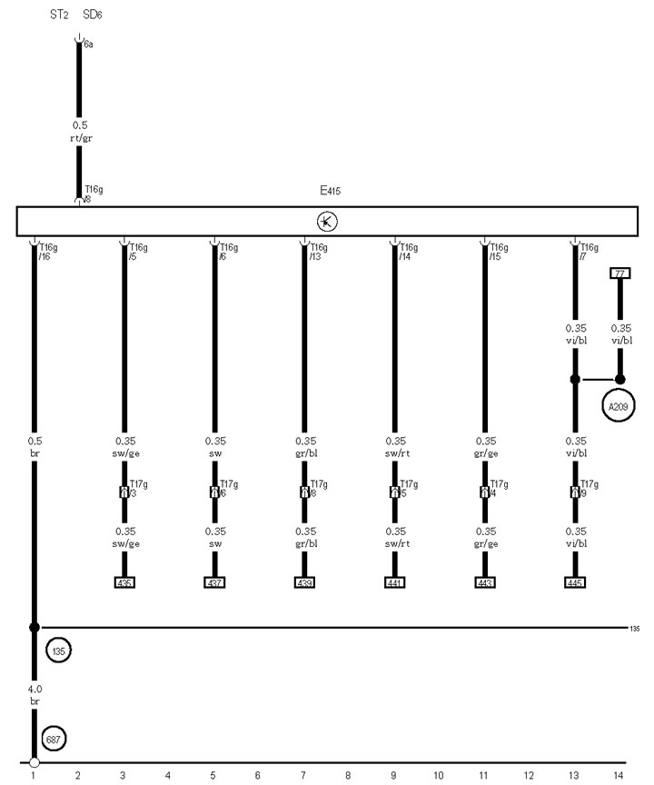
21-1 Entry and Engine Start Authorization Switch, Fuse #6 in Holder D
21-2 Control unit in instrument panel insert, radio clock
*2 Since May 2009.
*3 Before April 2009 issue.
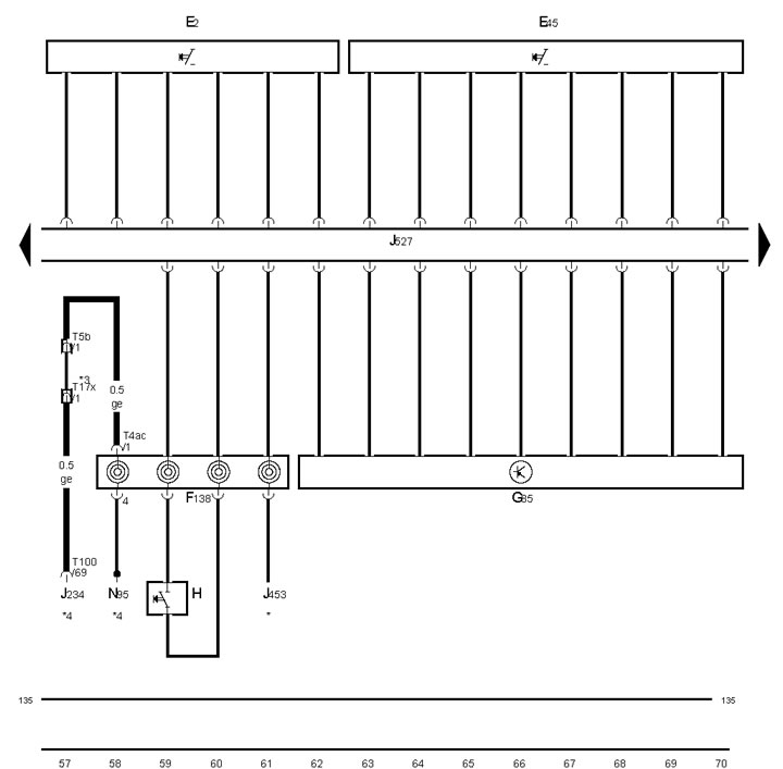
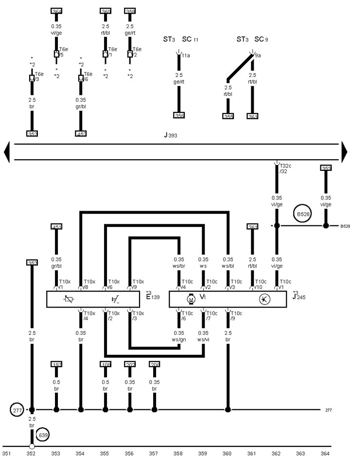
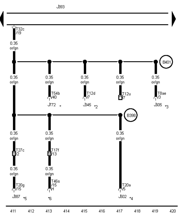
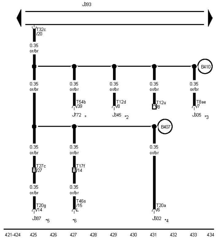
21-3 Fuel level sensor, fuel supply pump, control unit in instrument panel insert
*Depending on equipment
*2 See ECM diagram
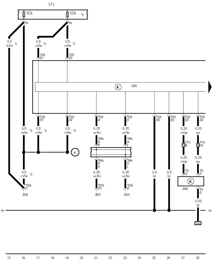
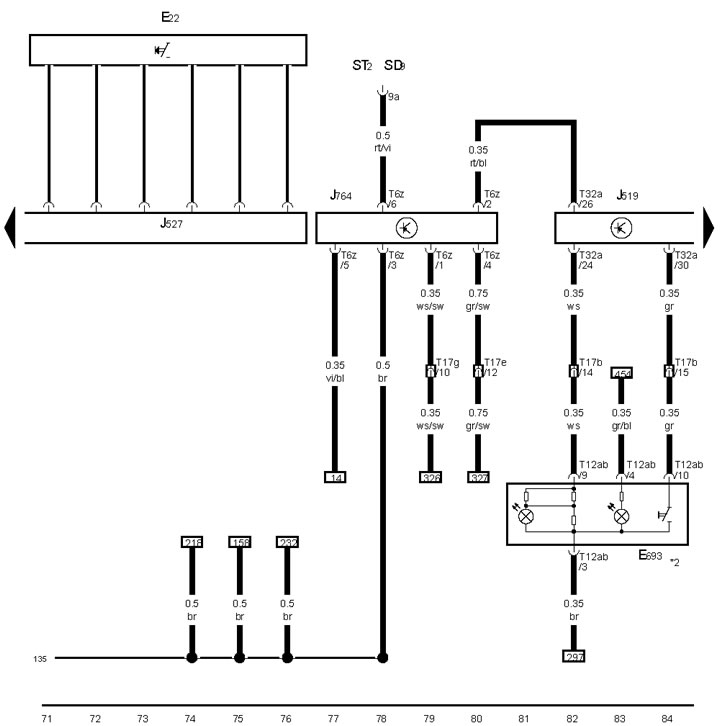
21-4 Steering column electronics control unit
*2 See ECM diagram
*3 Brown insert bridge on front passenger side
*4 CAN bus wire
21-5 Direction indicator and cruise control switches, steering column electronics control unit
*See multifunction steering wheel diagram
*2 Before April 2009 issue.
*3/*4 Since May 2009 /see SRS diagram
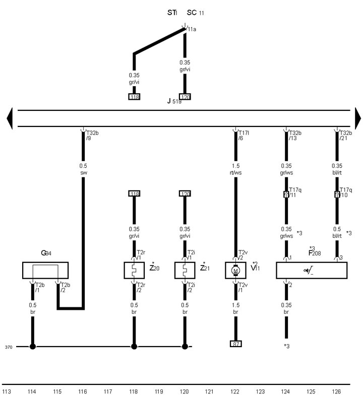
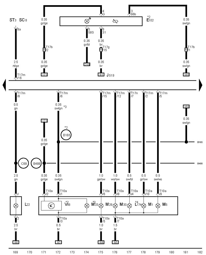
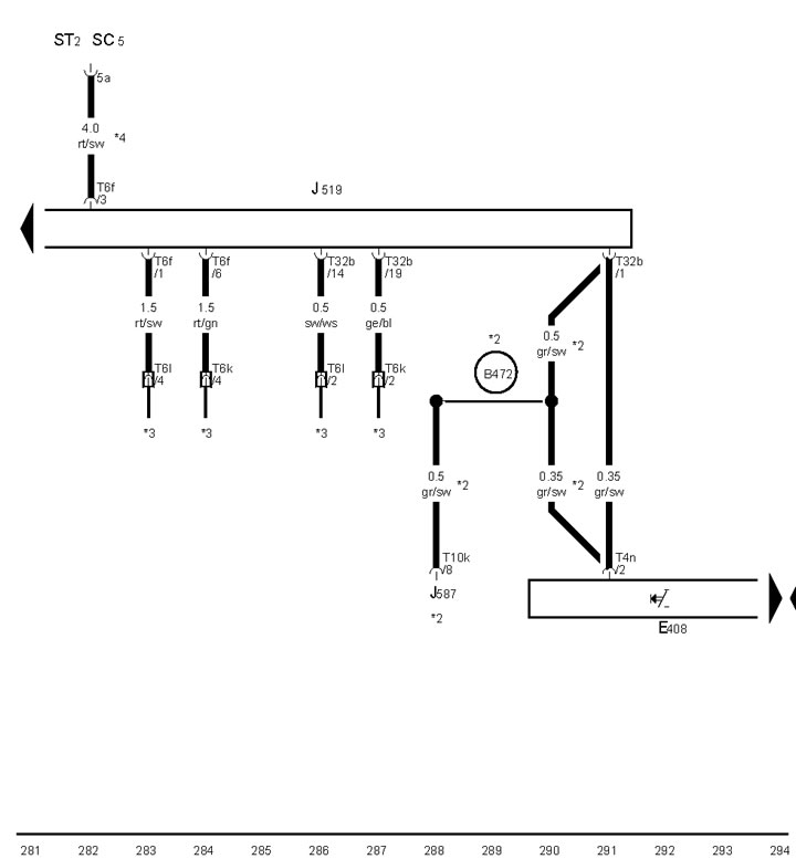
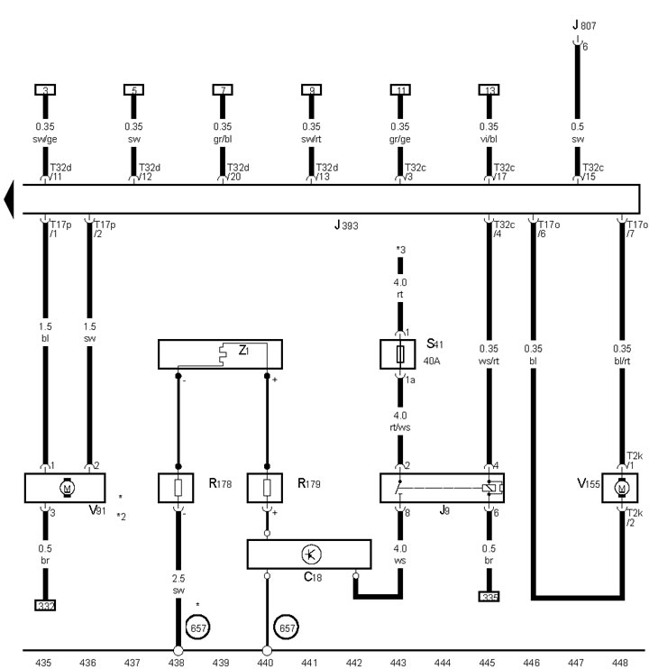
21-6 Windscreen wiper switch, start button, steering column electronic control unit, electronic steering column lock module
*2 Models with system "Stop/start"
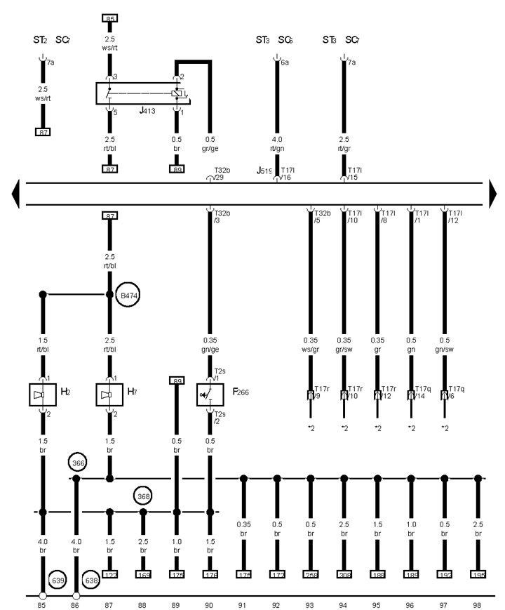
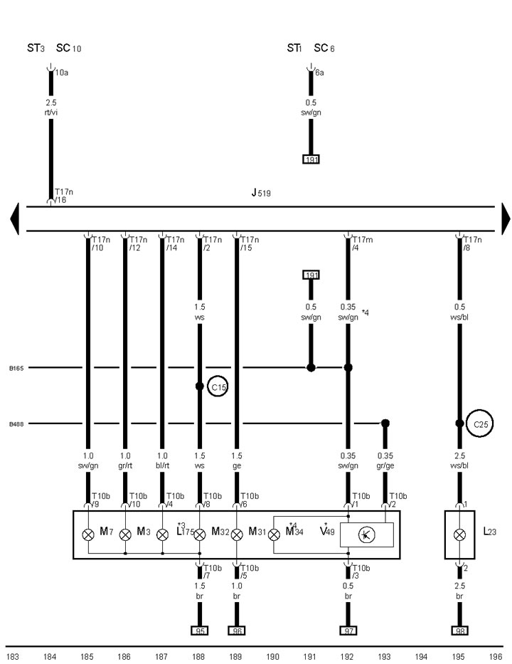
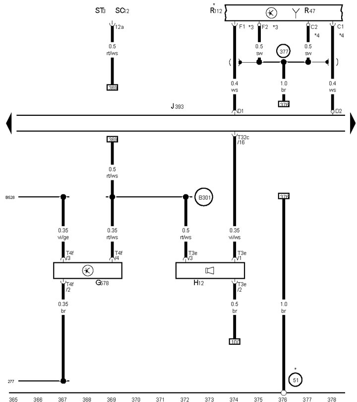
21-7 Hood contact switch, horns and their relays
*2 See ECM diagram
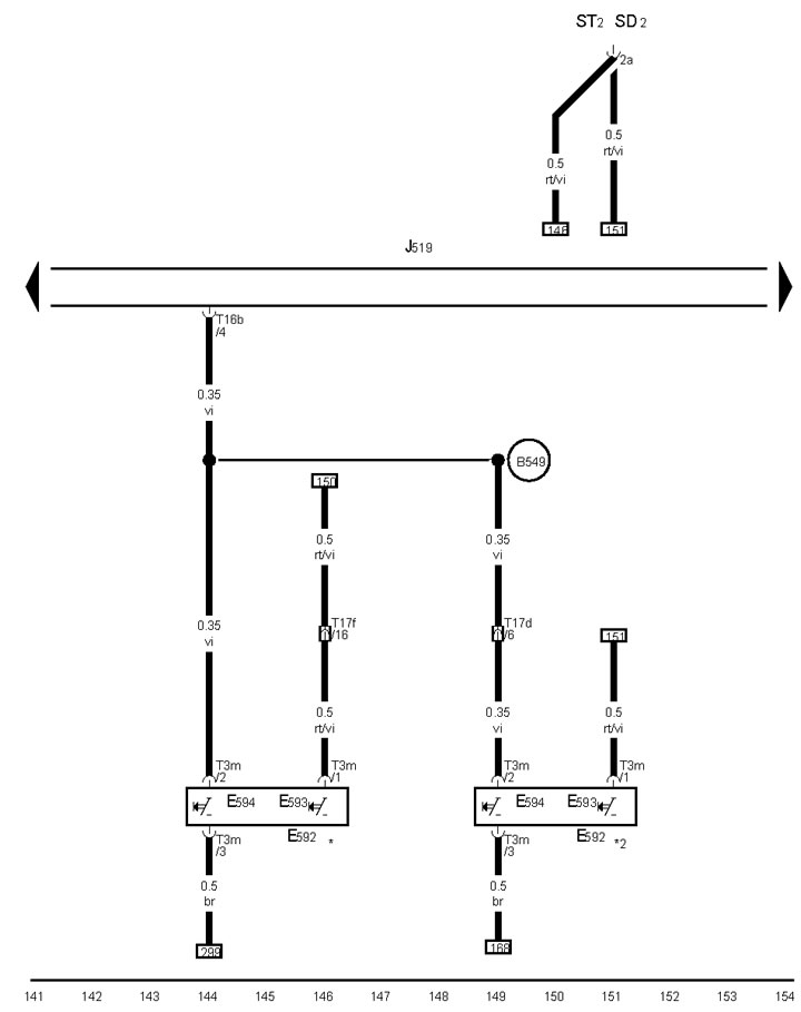
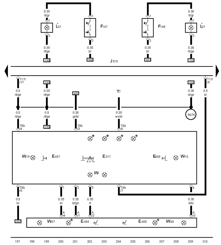
21-8 Rain and light sensor, windscreen wiper control unit
*/*3 LHD/RHD Models
*4 Brown insert bridge on driver side
*5/*6 From May 2009 issue / until April 2009 issue.
*7 CAN bus wire
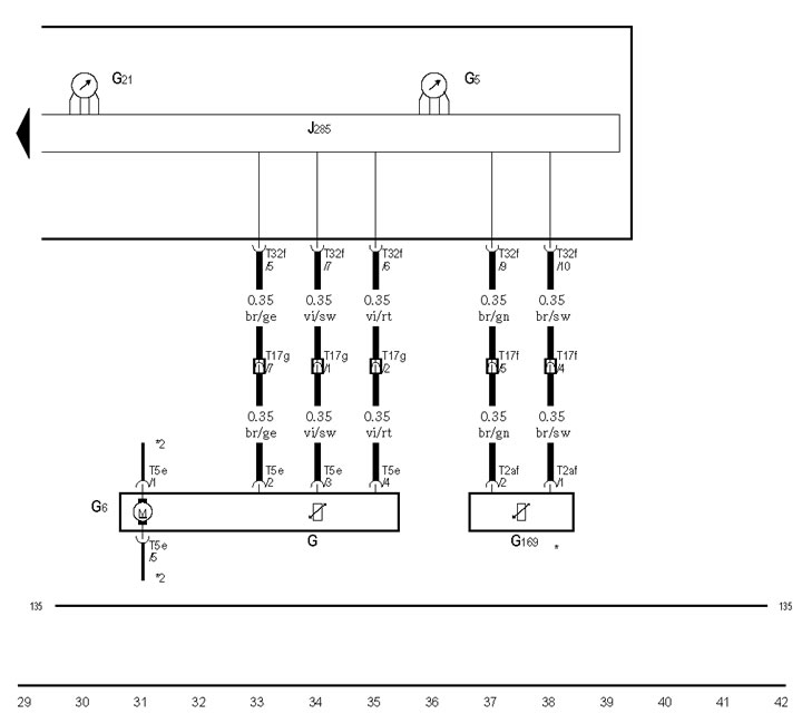
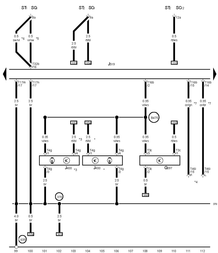
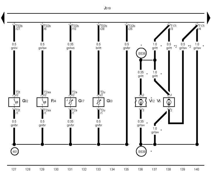
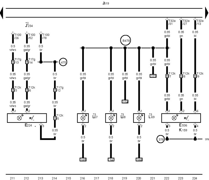
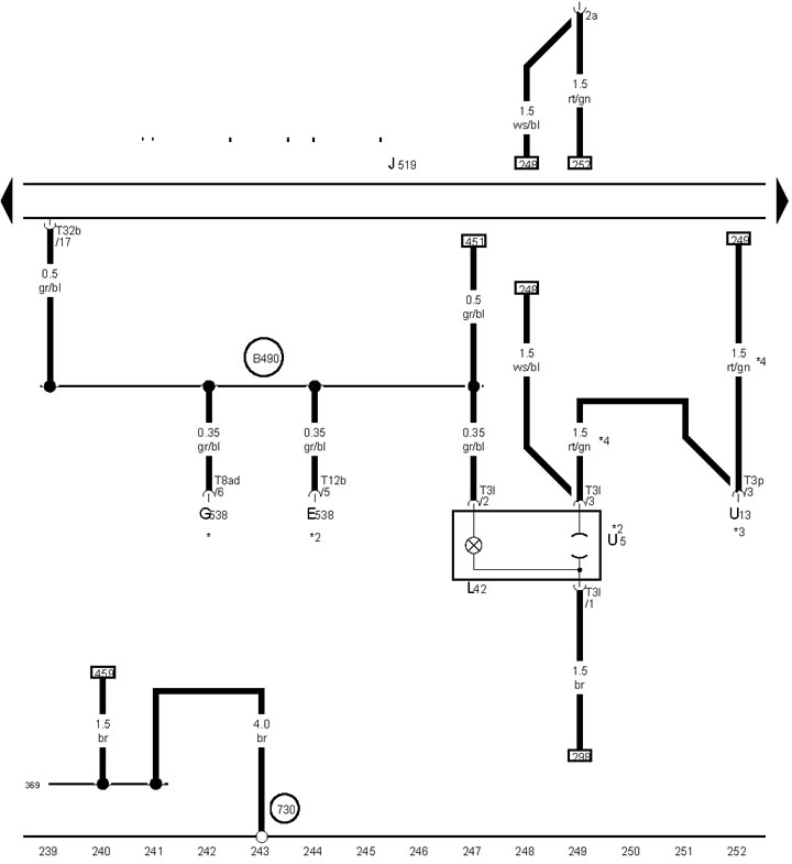
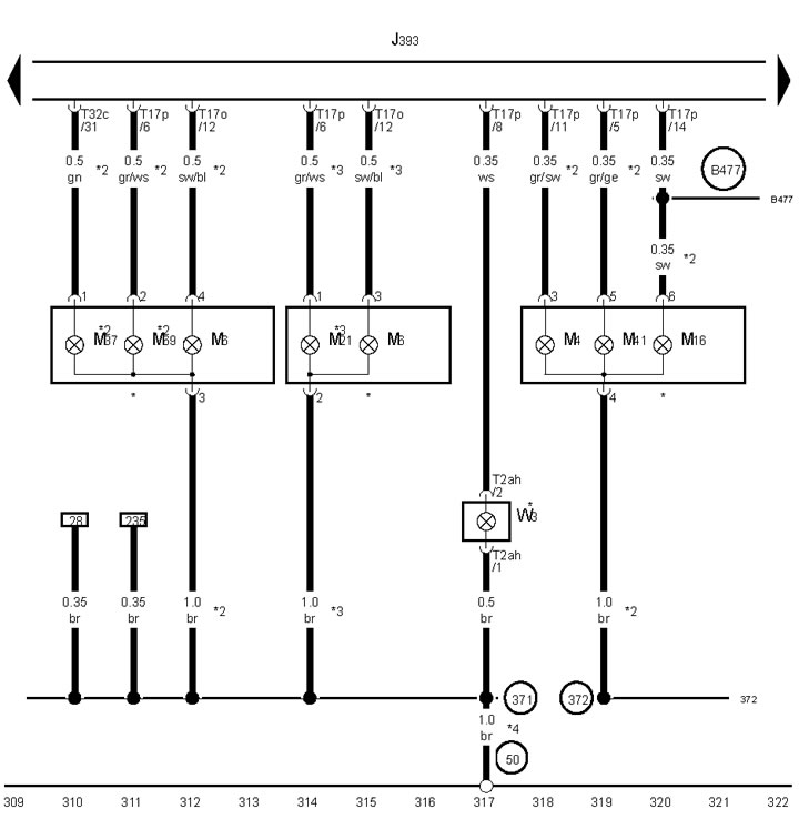
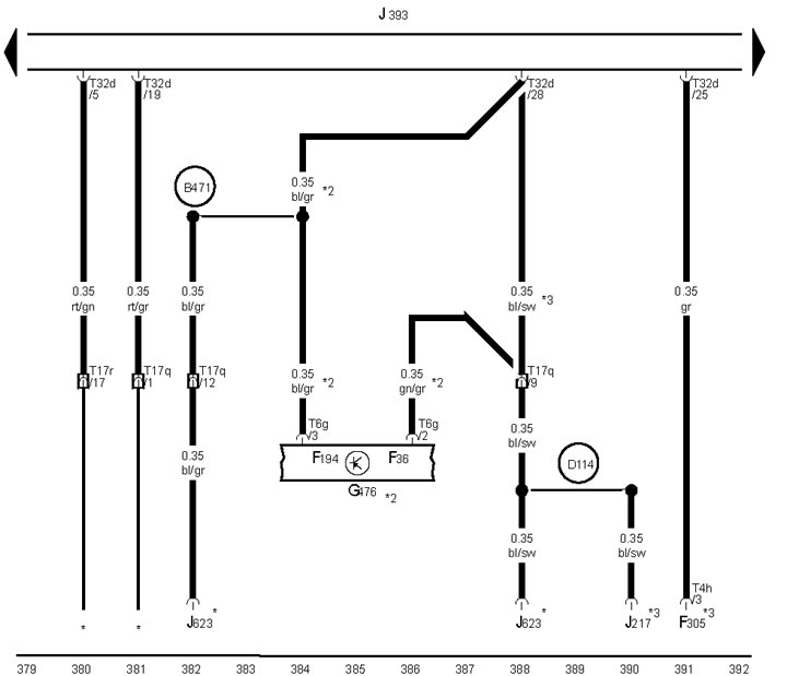
21-9 Gear sensor, front left brake pad wear sensor, headlamp washer pump, windshield washer nozzle heaters
* Models with heated windshield washer nozzles
*2 Models with headlight washer
*3 See ECM diagram
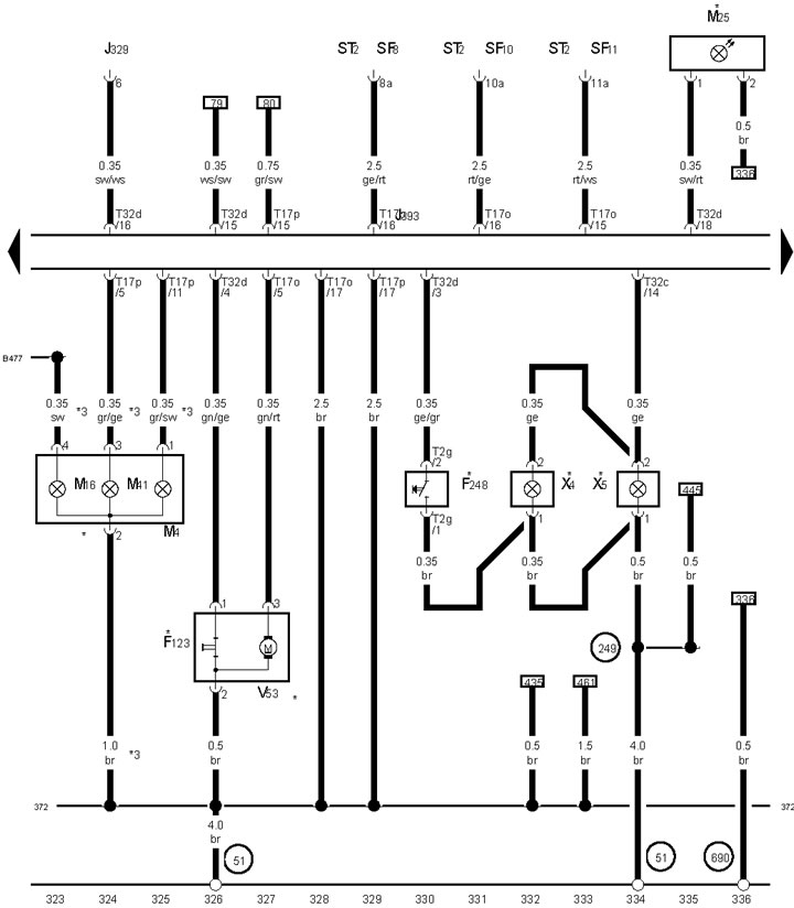
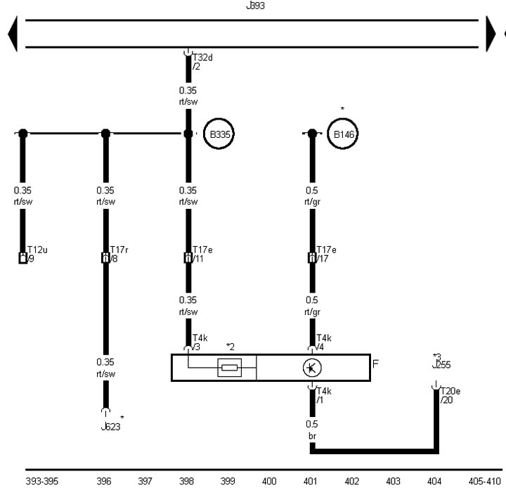
21-10 Low brake and coolant fluid level sensors, outside air temperature sensor, washer fluid reserve sensor, rear window wiper motor
*/* 2 Station wagon/Sedan
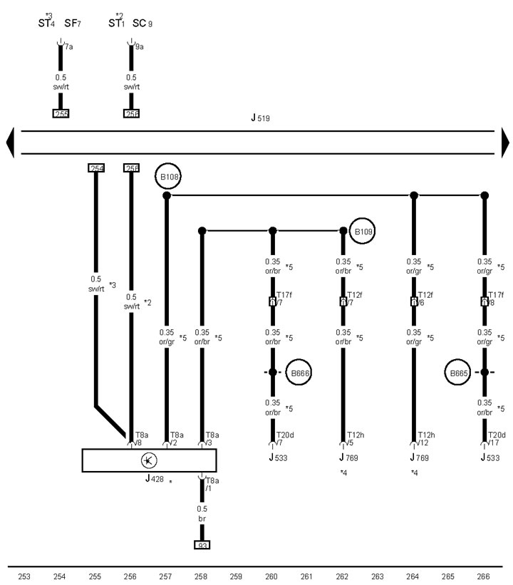
21-11 Switch Model for "Charisma"
* Models without navigation system
*2 Voice output with radio/navigation system
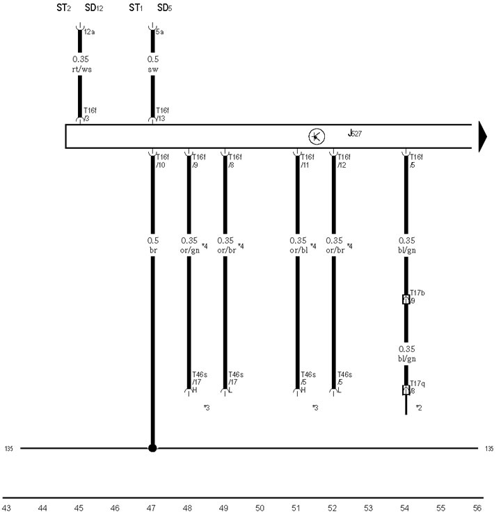
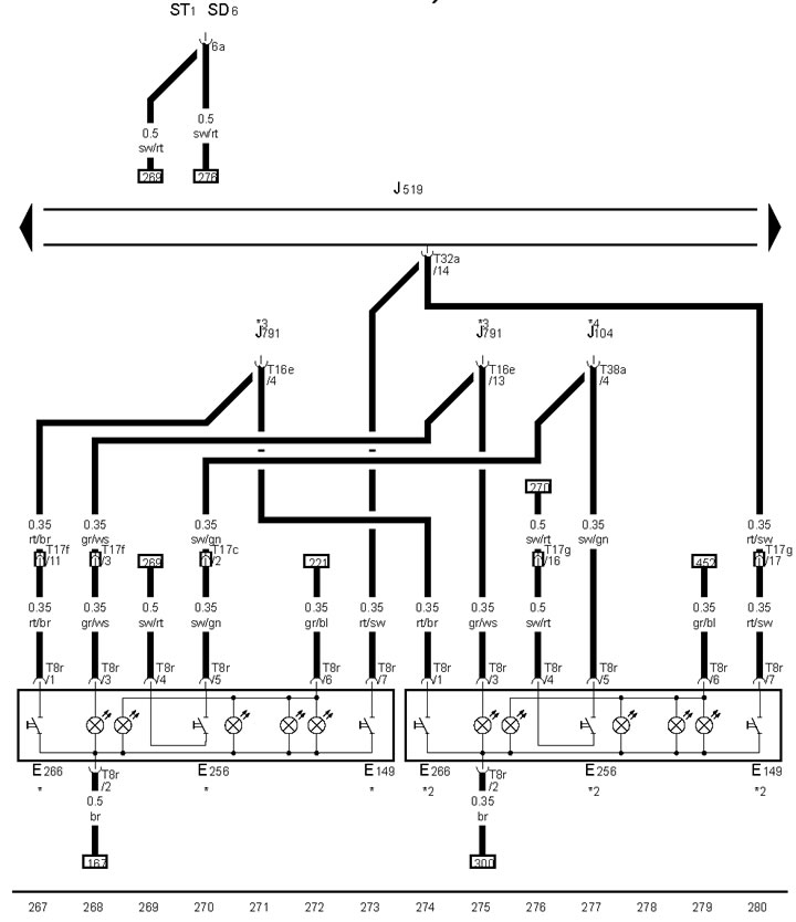
21-12 Light switch, hazard warning switch
*2/*3 Until April 2009/since May 2009.
*4 See diagram S
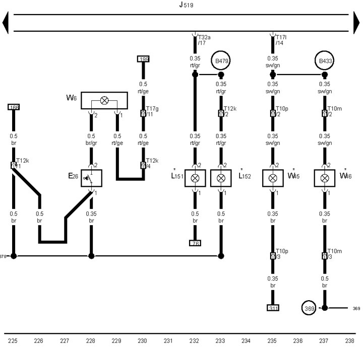
21-13 Left direction indicator and high beam lamp
*2 Except US models
*3 US Models
*4 Models with DRL
21-14 Right headlight high beam lamp
* Except US models
*3 Models with DRL
*4 US Models
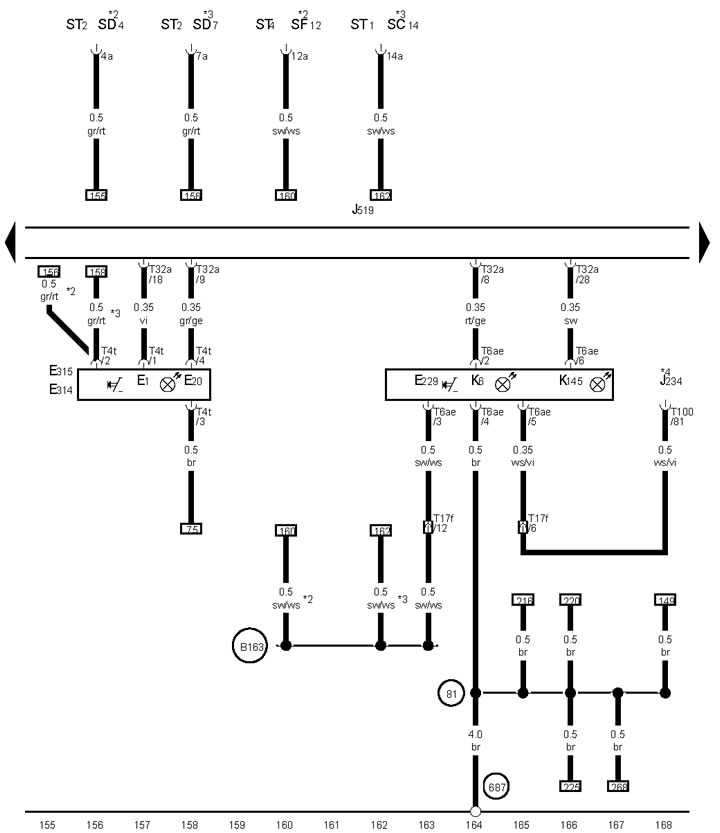
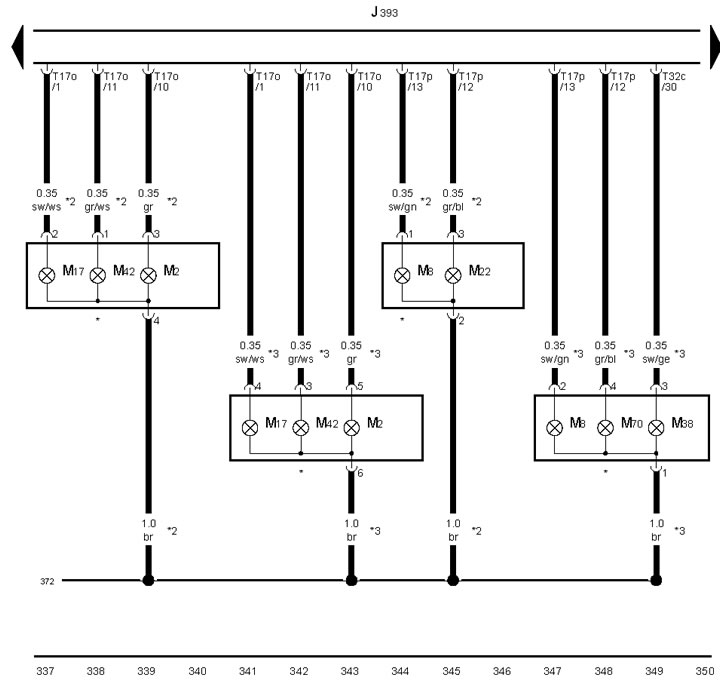
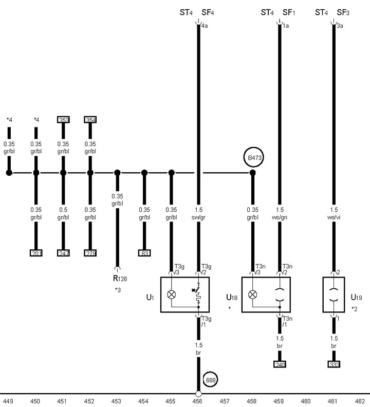
21-15 Rear left reading lamp, vanity mirror light, front and rear interior lights
*Depending on equipment
21-16 Front passenger airbag switch, button and K/L hotel parking
* Models with airbag switch
*2 See SRS diagram
*3 Depending on equipment
21-17 Glove box light switch, glove box and footwell lighting
*Depending on equipment
21-18 Socket No.1 12 Volt
*See climate system diagram
*2 Depending on education
*4 Models with transformer
21-19 ACC control unit
* Models with ACC
*2/*3 From May 2009 issue/until April 2009 issue.
*4 Models with system "Lane assist"
*5 CAN bus wire
21-20 Rear curtain switch, TCS and ESP switch, Parking assist switch
* Models with Low navigation system
*2 Models without navigation system
*3 Only models with parking assist system
*4 See ABS diagram
21-21 Engine entry and start authorization switch
*2 Models with AT/CVT/DSG
*3/*4 See seat heating diagram
21-22 Entry and engine start authorization switch, front outside door handle contact sensors, comfort control unit, left entry and engine start authorization antenna
21-23 Comfort systems control unit, left side light, left side light/brake light, luggage compartment lighting
* Sedan
*2/*3 US/Other Models
*4 Possible section 1.5
21-24 Comfort systems control unit, electric motor for single lock of luggage compartment lid
* Sedan
*3 Except US models
21-25 Control unit for comfort systems, right rear side light and turn signal lamps
* Sedan
*2 Except US models
*3 US Models
21-26 Switch, electric motor and control unit for the upper hatch, control unit for comfort systems
* Station wagon
*2 See the corresponding diagram
*3 Sedan
21-27 Sensors: anti-theft alarm siren, comfort systems control unit, single lock and anti-theft alarm antenna
* Sedan
*3 See MMI diagram
*4 Depending on equipment
21-28 Clutch pedal sensor, comfort control unit
*See ECM diagram
*2 Models with manual transmission
*3 See diagram AT/CVT/DSG
21-29 D/W brake lights, comfort control unit
*See ECM diagram
* 2 Coil D/W brake lights
* 3 See the climate system diagram
21-30,21-31 Comfort systems control unit
* Models with rear view camera
*2 Models with trailer socket
*3 Station wagon
*4 Models with tire inflation pressure control
*5 See comfort systems diagram
*6 Brown insert bridge on front passenger side
21-32 Comfort systems control unit, rear curtain electric motor, fuel filler flap locking electric motor, rear window heating
* Sedan
*2 Models with rear curtain
21-33 Cigarette lighter, sockets No.2 and No.3 12 Volt
*Depending on equipment
*2 Models with power outlet in luggage compartment
*3 See diagram phone
*4 See seat heating diagram