
This Chapter describes the maintenance and repair procedures for certain components of the on-board electrical system, which include, in addition to the specific ones discussed below, all lighting fixtures and electrical accessories not directly related to the engine. In addition, diagnostic procedures for general electrical faults are discussed. Information on the battery, alternator, and starter is provided in Chapter Engine electrical systems.
Caution: When performing any repair or maintenance work on electrical components, it is imperative to first disconnect the battery ground cable to avoid electrical shock and/or fire.
Warning: Individual characteristics are also given in the text of the Chapter and, if their implementation is mandatory, are highlighted in bold.
12V incandescent lamps
|
Purpose |
Base, Type |
Power, W |
|
High beam |
H7 |
55 |
|
Low beam, halogen/xenon |
H7/D2S |
55/35 |
|
Fog lights |
H11 |
55 |
|
Parking light |
W |
5 |
|
Front direction indicators |
PY |
21 |
|
Side turn signal repeaters |
WY | 5 |
|
Rear direction indicators |
PY | 21 |
|
Side lights |
R | 5 |
|
Brake lights |
R | 21 |
|
Fog lights |
R | 21 |
|
Reversing lights |
R | 21 |
|
License plate lights |
WITH | 6 |
|
Reading light |
R | 6 |
|
Ceiling lamp front |
WITH | 10 |
|
Interior/ trunk lighting shades |
WITH | 6 |
|
Storage box/trunk |
W | 5 |
|
Footwell/entrance area lighting |
W |
5 |
|
Characteristic |
Meaning |
|
H7/H11 |
Halogen lamp |
|
D2S |
High voltage xenon lamp |
|
R |
Bayonet socket |
|
W |
Glass base |
|
WITH |
Soffit |
|
Y |
Color orange |
Electrical fuses
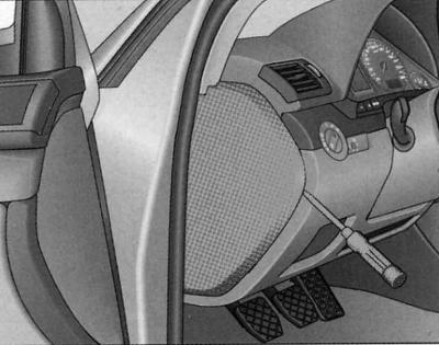
Fuse box cover. Left end side of instrument panel
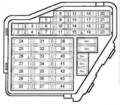
Fuse board in the instrument panel
Coloured markings of fuses
|
Color |
Maximum current, A |
|
Light brown |
5 |
|
Red |
10 |
|
Blue |
15 |
|
Yellow |
20 |
|
Natural (white) |
25 |
|
Green |
30 |
Purpose of fuses
Some of the consumers listed are specific to certain models or are included in the custom package. In case of discrepancies, the data provided on the sticker on the inside of the fuse cover shall prevail.
|
№ |
Consumer |
Current strength, A |
|
1 |
Air conditioner |
10 |
|
2 |
Footwell Lights |
5 |
|
3 |
Heated windshield washer jets |
5 |
|
4 |
Cooling system fan |
5 |
|
5 |
Telephone, Engine Oil Level Sensor, Multi-Function Switches, Rear Seat Heating, Rear Window Sunshade, Automatic Transmission (gear shift linkage) |
10 |
|
6 |
Air conditioner (air quality sensor), pressure sensor |
5 |
|
7 |
Electronic skid control system (ESP), brake light switch, clutch pedal sensor, steering wheel angle sensor |
10 |
|
8 |
Telephone |
5 |
|
9 |
Brake booster (vacuum pump) |
15 |
|
10 |
Automatic headlight range control |
10 |
|
11 |
Absent |
|
|
12 |
Diagnostic socket |
10 |
|
13 |
Steering column module |
10 |
|
14 |
Brake signal lights |
10 |
|
15 |
Instrument panel, navigation system |
10 |
|
16 |
Garage door opener |
5 |
|
17 |
Parking assistance, ride height adjustment, tire pressure monitoring |
10 |
|
18 |
Absent |
|
|
19 |
Fog lights, rear fog lights |
15 |
|
20 |
Right low beam headlight, headlight range adjuster |
15 |
|
21 |
Left low beam headlight, headlight range adjuster |
15 |
|
22 |
Driver's door |
15 |
|
23 |
Front passenger door |
15 |
|
24 |
Comfort electrical equipment with single control |
20 |
|
25 |
Heater fan |
30 |
|
26 |
Rear window heating |
30 |
|
27 |
Trailer socket (control unit) |
30 |
|
28 |
Fuel pump, additional pump for diesel engine |
20 |
|
29 |
Engine management |
20 |
|
30 |
Lift and slide roof panel |
20 |
|
31 |
Reversing lights, automatic transmission, diagnostic socket, auto-dimming interior mirror |
15 |
|
32 |
Engine management |
20 |
|
33 |
Cigarette lighter |
15 |
|
34 |
Engine management |
15 |
|
35 |
Socket in the trunk |
30 |
|
36 |
Wiper |
30 |
|
37 |
Windshield and headlight washer pump |
25 |
|
38 |
Comfort electrical equipment with single control, trunk release |
15 |
|
39 |
Radio system |
20 |
|
40 |
Sound signal |
25 |
|
41 |
Absent |
|
|
42 |
Electronic skid control system (ESP) |
|
|
43 |
Engine management |
15 |
|
44 |
Heated seats |
30 |
Power windows and seats are controlled overload protection devices for electrical circuits. After the overload has been eliminated (for example, in case of frozen glass) they turn on again automatically after a few seconds.
Relay
Central micro relays
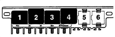
- 1 - Horn relay
- 2 - Load reduction relay
- 4 — Fuel pump relay
- 5, 6 — Windscreen wiper/washer interval mode relay
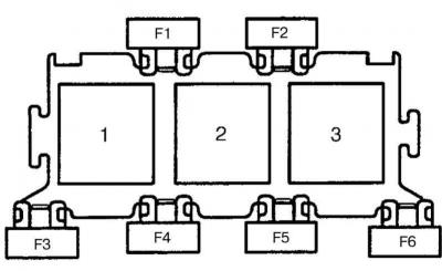
8-slot relay block
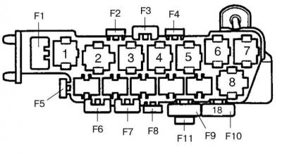
- 2 — Second speed control relay for the cooling fan
- 3 — Cooling fan control relay (1st speed)/coolant pump control
- 4 — White power window/sunroof control unit/ABS relay (with ESP)
- 5 — Open door warning signal control unit
- 7 — Radio/CD changer/ABS pump relay
- F2 — Passenger seat electrics
- F3 — Driver's seat electrics
- F5 — Additional power connector
- F6 — Front electric window circuit protection
- F7 — Rear electric window circuit protection
- F8, F9, F11 — Radiator fan relay and control unit
- F10 — ABS
3-way relay block
- 1 — Relay 2 for coolant heating (diesel)
- 2 — Additional air supply relay/Relay 1 for coolant heating (diesel)
- 3 — ECM Power Relay
- F1 —
- F2 — ECM
- F4 — Heater 2 coolant (1.9 TDI)/Secondary air pump/glow plugs (2.5 TDI)
- F5 — Heater 1 coolant (1.9 TDI)
- F6 - Glow plugs (diesel)
13-way relay block
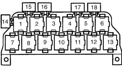
- 3 — K/V clutch relay
- 4.5 — Rear light control unit
- 6 — Selector lever illumination relay
- 7 — Fog lights relay
- 8 — DRL enable relay
- 9 — Daytime running lights relay
- 13 - Park/Neutral position relay
Location of the main electrical elements in the body
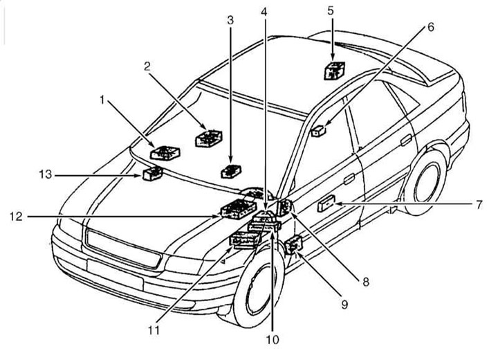
- 1 — Cruise control unit
- 2 — TCM
- 3 — Airbag control unit
- 4 - 13-way relay block
- 5 — Anti-theft alarm/interior lighting/single lock control unit
- 6 — Ultrasound sensor control unit
- 8 — Fuse panel
- 9 - Left connection block
- 10 - Central micro relays
- 11 - 8-way relay block
- 12 — ECM
- 13 - Right connection block
(The original publication in its entirety is posted on the website «AudiManual»)