
Table of contents: Removal ↓ Installation ↓
Removal
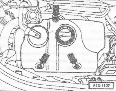
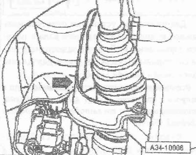
Remove the engine hood. Remove the engine cover "arrows".
Remove the noise insulation screen located below; to do this, disconnect the crankcase ventilation hose.
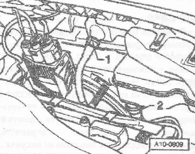
Remove the dipstick from the guide tube. Remove the dipstick guide tube. Ignore pos. "2". Remove the right front wheel. Remove the noise insulation screen "arrows". Install the oil pumping device "V.A.G 1782" under the engine. Drain the oil. Drain the transmission oil. Disconnect the plug connector of the oil level and temperature sensor "G266". Release the electrical wiring leading to the oil level and temperature sensor "G266" and to the engine speed sensor "G28" from the oil filter holder.
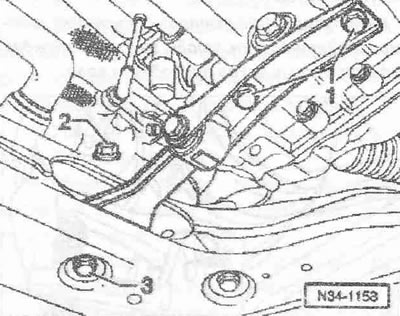
Unscrew bolts "1" and "3" and remove the engine spore. Ignore item "2".
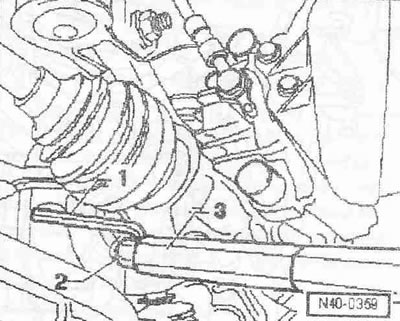
Unscrew the heat shield "arrow" of the right drive shaft.
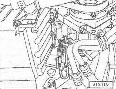
Unscrew bolt "1" securing the connecting rod to the support arm "2".
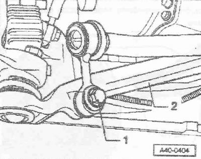
Hold the right support arm nut with a 5 mm Allen key and loosen it.
1. 5mm Allen key, handle shortened by 10mm. 2. Ring installation tool. 3. Torque wrench "V.A.G 1331".
Install the joint puller "1" as shown in the figure and push out the right support arm.
Instructions: When installing the hinge puller, make sure that the corrugated cover of the drive hall is not damaged.
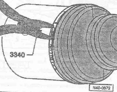
For reinstallation, mark the mounting position of the drive shaft to the flanged axle shaft on the gearbox. On the gearbox side of the dust cover, loosen the hose clamp using pliers "3340".
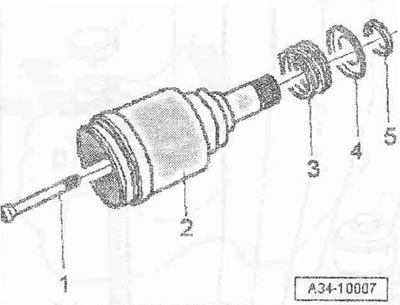
Caution! When removing the drive shaft from the flanged axle shaft, balls may fall out. Protect the balls from falling out with adhesive tape.
Tilt the shock absorber outward and remove the drive shaft from the flanged axle shaft. Tie the drive shaft to the side member.
Instructions: When removing, be careful not to damage the surface of the drive shaft.
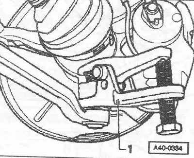
Unscrew bolt "1" and remove the axle shaft with flange "2" together with spring "3", washer "4" and cone "5" from the gearbox.
Remove the upper bolt of the dipstick guide tube from the oil filter holder. Unlock the right air duct mount on the oil pan. Remove the bolts securing the oil pan to the gearbox "arrows".
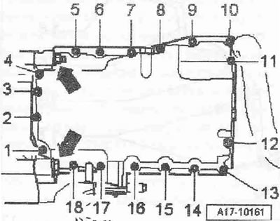
Loosen bolts "1...18" crosswise and unscrew them. Remove the oil pan, using a rubber hammer if necessary.
Installation
Installation is in reverse order, removing any remaining sealant from the oil pan and cylinder block, for example with a rotating plastic brush. Clean the mounting surfaces; there should be no oil or grease on them. Cut off the tube tip at the front mark (About holes approx. 2mm). Apply sealant to the clean oil pan seating surface as shown.
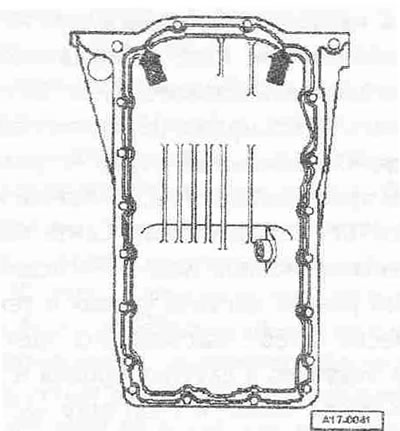
Thickness of sealant bead: 2...3 mm.
Instructions. The sealant bead should not be thicker than 3 mm, otherwise excess sealant may get into the oil pan and clog the mesh filter in the oil intake pipe. In the area of the rear sealing flange "arrows" the sealant should be applied especially carefully. The oil pan should be installed within 5 minutes after applying the sealant.
Immediately install the oil pan and tighten the mounting bolts to 5 Nm.
Tighten the oil pan mounting bolts to the gearbox.
Instructions. When installing the oil pan with the engine removed, make sure that the pan is flush with the cylinder block. After installing the oil pan, the sealant must dry for about 30 minutes. Only then can the oil be added.
Install the drive shaft. Install the support arm. Install the engine support. Fill with oil and check its level. Fill with transmission oil.
Tightening torques:
- Oil pan to cylinder block: 15 Nm
- Oil pan to gearbox: 45 Nm
- Oil drain plug thread: 30 Nm
- Oil dipstick guide tube to oil filter holder: 10 Nm
[The original article is available on the website audimanual.ru]