
Withdrawal
Instruction. The engine is removed together with the gearbox in the forward direction. During installation, install in the same places all binders removed or cut off during removal. Observe precautions when disconnecting the battery ground. The battery is located in a special trunk compartment.
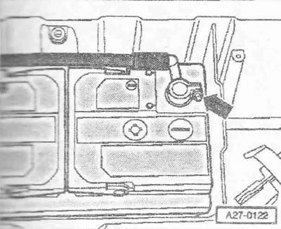
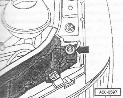
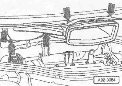
Switch off the ignition and remove the key from the ignition lock. Disconnect cable "masses" -arrow- from the battery. Remove the engine hood.
Attention! When opening the cap, hot steam or hot coolant may come out of the expansion tank, wrap the cap with a rag and carefully open the tank.
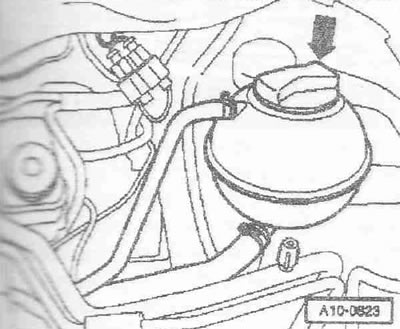
Open cap -arrow- of expansion tank.
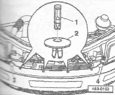
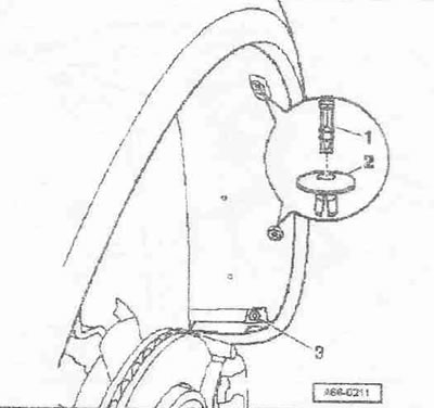
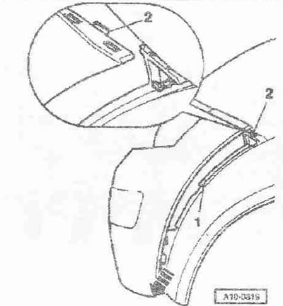
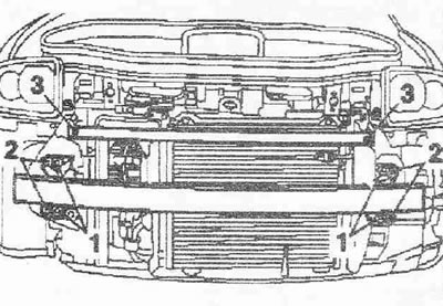
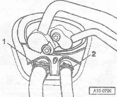
Instruction. To release and remove the clips, push the pins -1- into the retaining clips approx. by 4 mm. Do not insert pins all the way.
Release retaining clips on bumper trim. Release screws -3- and -4-.
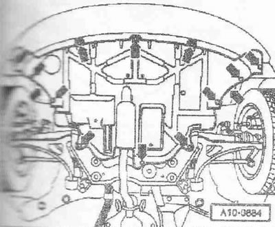
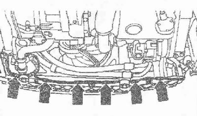
Remove front wheels. Remove noise insulation -arrows-.
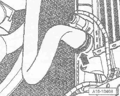
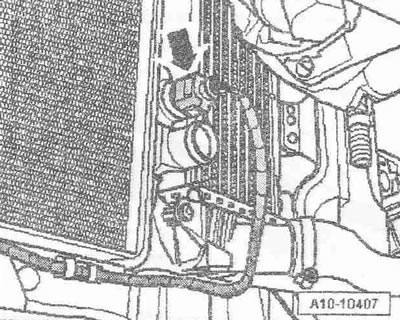
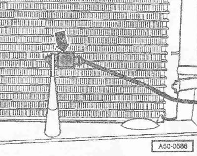
Place a pallet for service cranes -VAS 6208- under the engine. Detach lower coolant hose from radiator -arrow- and drain off coolant.
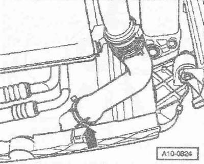
Remove air duct from intercooler -arrow-.
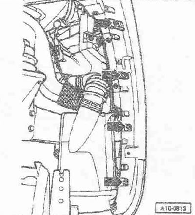
Release retaining clips on fender liner. Remove bolt -3-. Remove the front part of the left and right fender liner.
Remove bolts -arrows- from bumper cover. Mark the position of the bolts for reinstallation.
Press bumper cover -arrow- out of groove from bottom. Detach top section from inside -2-. Remove bumper cover. Disconnect plug connectors for fog lights (in the presence of). Lay bumper cover on soft pad.
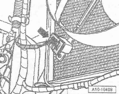
Unplug electrical connector -arrow- for thermostatic switch for radiator fan -F18-.
Unplug electrical connector -arrow- for radiator fan -V7-.
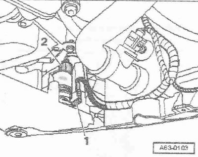
Unplug electrical connector -2-. Detach water hose -1- from washer pump and close fitting with a suitable plug.
Unbolt lower wiring harness from radiator carrier -arrows-.
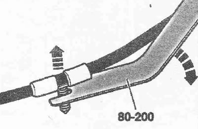
Use lever -80-200- to release wiring harnesses. To facilitate removal, if necessary, use a silicone-free spray.
Disconnect the horn connector. Unscrew 2 bolts -3- left and right each and remove reinforcement strip. Pry off and remove lock washers -2-. Unscrew left and right bolts -1- and remove bumper safety bar.
Unscrew securing bolts -arrows- for radiator brackets on left and right.
Unplug electrical connector -arrow- for outside temperature sender -G17-. Unplug electrical connector at washer fluid level warning sender -F77-. Disconnect the wiring harness from the left air duct; use the lever -80-200- to remove the fasteners.
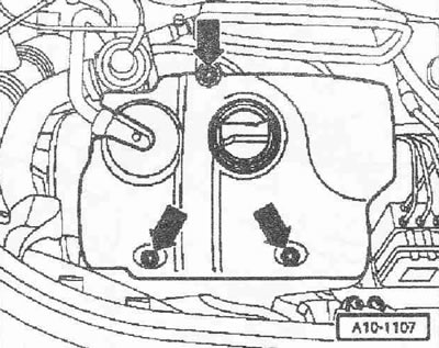
Remove engine cover -arrows-. Remove the noise shield below by disconnecting the crankcase ventilation hose.
Detach vacuum hose -1-. Detach air duct -2- from air mass meter -G70-.
Unplug electrical connector -1- for intake manifold pressure sender -G71- and move wiring clear. Remove air hose -2- connecting intercooler and intake manifold.
Unplug electrical connector -arrow-of headlights on left and right sides of vehicle. Remove the wire binders leading to the right headlight from the radiator frame. Use the lever -80-200- to remove the fasteners.
Remove bolts -arrows- and remove bonnet cable.
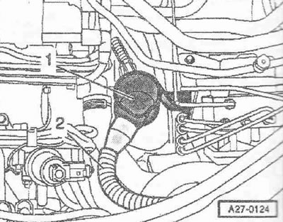
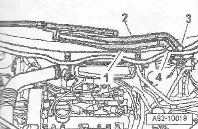
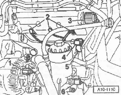
Unplug electrical connector -3- at bonnet limit switch -F266-. Loosen the wiring harness on the radiator frame, use the lever -80-200- to remove the fasteners. Remove the oil dipstick from the guide tube. Remove guide tube -4- for oil dipstick: radiator frame. Remove oil filler pipe -5- from oil tank. Pos. -1- and -2- are ignored.
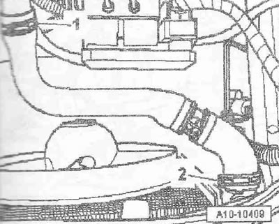
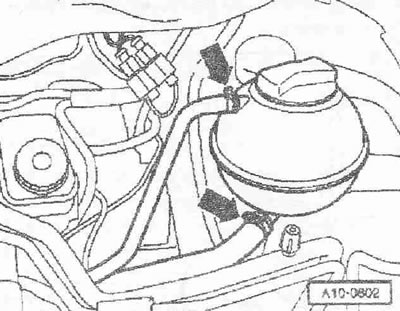
Detach drain hose -2- from water tank -1-.
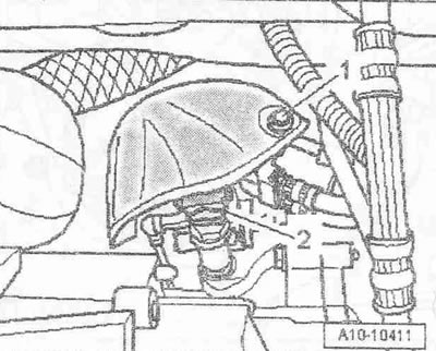
Detach the top left coolant hose at the location marked -1- from the coolant pipe. Pos. -2- ignore.
Remove bolt -arrow- on left and right.
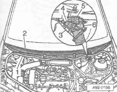
Remove the radiator frame and fix it in a stable position. Use a screwdriver to remove caps -3- and -4- from wiper arms. Loosen the nuts on both levers a few turns. Release levers -1- and -2- by tilting slightly on all wipers. Loosen nuts completely and remove wiper arms.
Disconnect the washer fluid pipe -3-. Unplug electrical connectors -4- and -5- for heated washer nozzles. Unclip hose clamp -6- using hose clamp pliers -VAG 1921- and detach drain hose from cowling grille. Remove rubber seal -1- for fairing grille. Remove fairing grille -2-. Release the washer fluid pipe.
Remove bolts and nuts -arrows-. Remove the fresh air intake duct and hang it over the right side of the vehicle.
Unplug electrical connector at oil level and oil temperature sender -G266-.
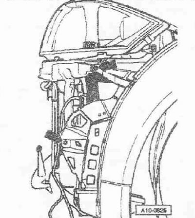
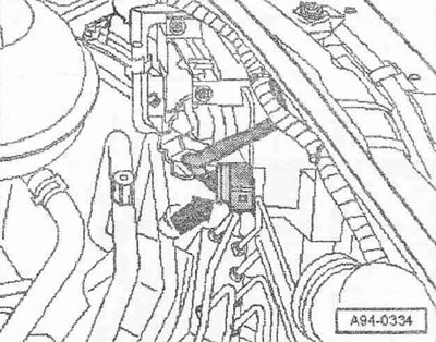
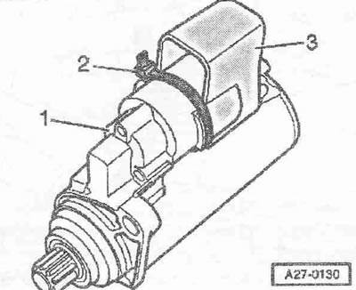
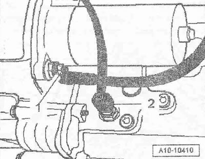
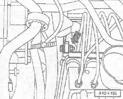
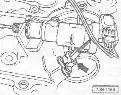
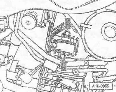
Cut off binder -2- and pull trim -3- upwards from solenoid switch -1-.
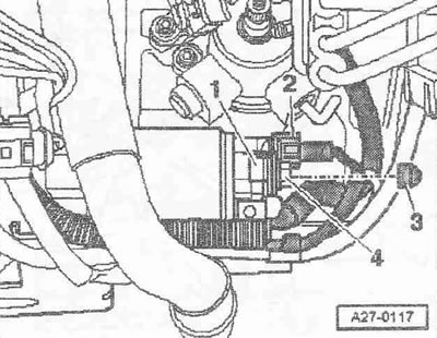
Remove cover -3-. Disconnect plug connector from terminal 50 -pos. 2- electromagnetic switch. Loosen nut -4- and remove positive wires. Pay attention to stopper -1-.
Loosen nuts and remove "mass" the wire. Unplug electrical connector -2- from reversing light switch -F4- and move wiring clear.
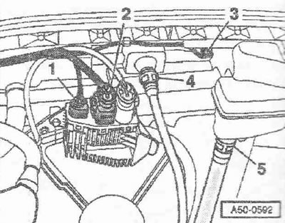
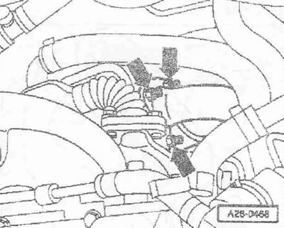
Disconnect plug connector from terminal D+ -pos. 1- generator. Unplug electrical connectors -2- for glow plugs. Pull out the pin and loosen the knurled nut -3- on the central connector of the unit injectors. Unplug electrical connector for Hall sender -G40- -pos. 4- and engine speed sender -G28- pos. -5-. Unplug electrical connector -6- for oil pressure sender -F1- and move wiring clear.
Detach coolant hoses from expansion tank -arrows-.
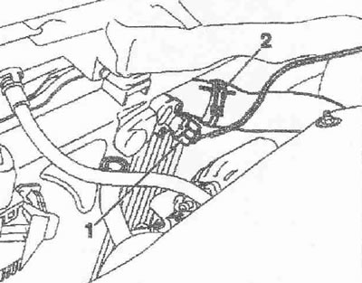
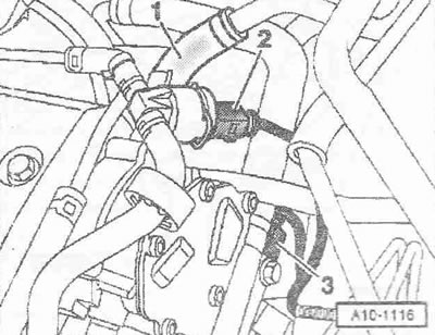
Disconnect vacuum hose -1- from tandem pump on brake booster. Unplug electrical connector -2- for fuel temperature sender -G81- and move wiring clear. Unplug electrical connector -3- for coolant temperature indicator sender -C2-/ coolant temperature sender -G62-.
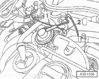
Detach vacuum hose -1- from mechanical EGR valve. Detach vacuum hose -2- from throttle valve control valve -N211-.
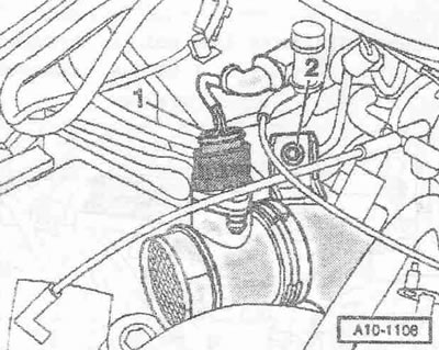
Unplug electrical connector -1- from air mass meter -G70-. Loosen nut -2-.
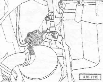
Detach vacuum hose -arrow- from vacuum pressure regulator, charge air.
Attention! The temperature of the fuel lines or fuel e/m, equipped with an engine with unit injectors, can reach 100°C. Allow fuel to cool before disconnecting fuel lines. Otherwise, severe burns may result.
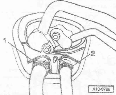
Mark and disconnect fuel pressure line -2- and fuel return line -1-.
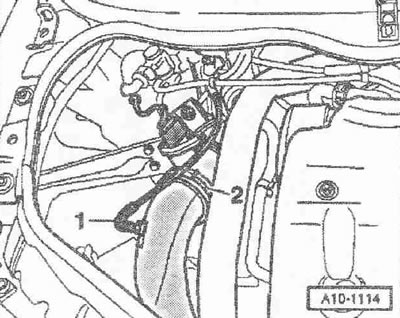
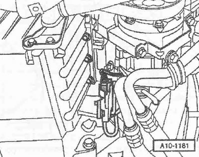
Mark the position of the supply hose -1- and the drain hose -2- in relation to the heat exchanger for the heater and remove the hoses from the front wall of the body.
Unbolt bracket for wiring harness from gearbox -arrow-.
Unscrew nuts -arrows- for precatalyst/turbocharger.
Unscrew bolt -1- on the heat shield of the gear selector.
Instruction. The heat shield is fixed with additional 2 bolts from the bottom, they will be turned out later.
Unplug electrical connector -2- for speedometer sender -G22-.
Unplug electrical connector -arrow- for gearbox speed sender -G38-.
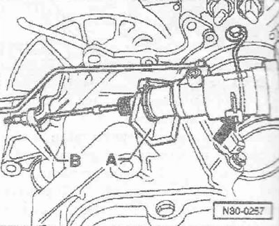
Loosen lock nut -B- and adjusting nut on clutch cable. Remove the clutch cable from the drive lever.
Instruction. Do not open the hydraulic connection of the clutch slave cylinder.
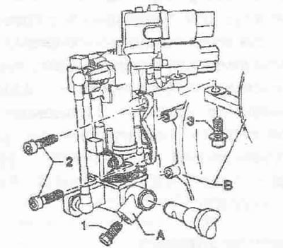
Unclip the connecting clip with the wire at the point indicated by -arrow- and remove the clutch slave cylinder from the stop -A-. Set clutch slave cylinder aside, do not open line system.
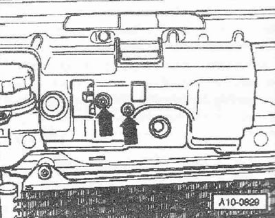
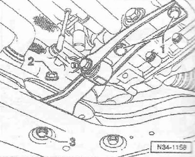
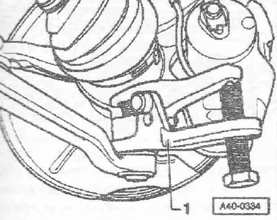
Remove bolts -1- and -3- and remove engine support. Pos. -2- ignore.
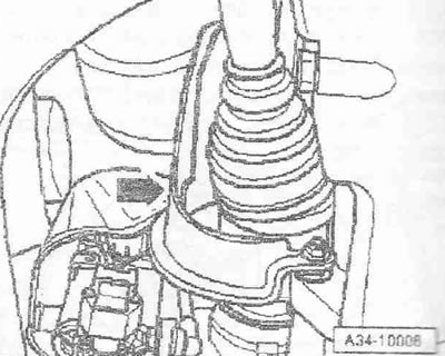
Unscrew heat shield -arrow- for right drive shaft.
Unscrew the bolt -1- fastening the connecting rod on the support arm -2-
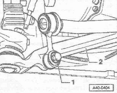
1. Allen key 5 mm, handle shortened by 10 mm.
2. Device for installing rings.
3. Torque wrench -VAG 1331-.
Hold the carrier arm nut with a 5 mm Allen key and loosen it.
Install joint puller -3287 A- -pos. 1- as shown in the figure and push out the carrier arm.
Instruction. When installing the joint puller, make sure that the bellows on the drive shaft are not damaged.
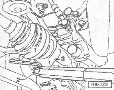
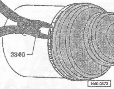
For reassembly, mark the installation position of the drive shaft to the flange shaft on the gearbox. Use pliers -3340- to release hose clamp on dust cover on gearbox side.
Carefully! When removing the drive shaft, balls may fall out of the flange shaft. Protect the balls from falling out with adhesive tape.
Tilt the spring strut outward and remove the drive shaft from the flange shaft. Repeat these operations on the opposite side of the vehicle. Tie up both drive shafts to the side member. Make sure that the surface protection of the shafts is not damaged. Loosen the lower bolts on the shifter heat shield.
Instruction. Do not open the hydraulic connections for the gear selector.
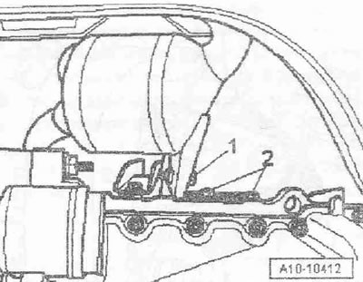
Loosen bolt -1- a few turns. Remove tappet -A- from selector shaft. Remove bolts -2- and -3-. Tie the shifter to the body as high as possible.
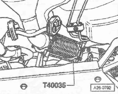
Instruction. The split piece between pre- and main catalytic converter must not be bent more than 10°. Risk of damage!
Support detachable element with locking tool -T40035-.
Remove bolts -2- on pre-catalyst bracket. Pos. -1- ignore. Disconnect the pre-catalyst from the turbocharger. Tie the pre-catalyst to the body.
Bolt front right load eye -T40016- to cylinder head.
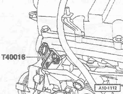
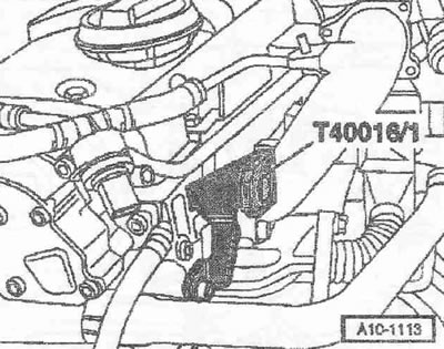
Screw rear left load eye -T40016/1- to cylinder head.
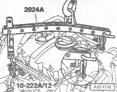
Install 2 eyelets -10-222 A/12- on rear left load eye -T40016- on cylinder head. Attach lifting device -2024 A- to engine and service crane -VA-S 6100- as shown.
Instruction. To equalize the position of the center of gravity of the power unit, the hook bars must be inserted as shown in the figure. The hooks and locking pins of the hanging device must be secured with cotter pins.
Raise engine slightly with service crane -VAS 6100-.
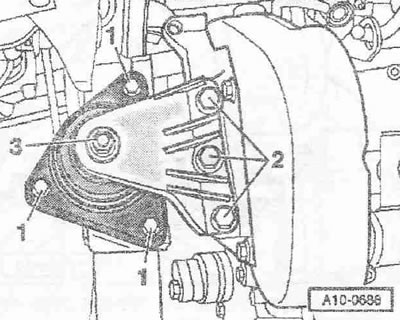
Instruction. Loosen nut -3- only after replacing engine mounting.
Remove bolts -1- and -2- and remove bracket with engine mount.
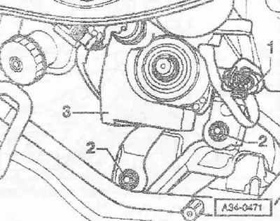
Loosen bolts -2- and tilt fuel unit -3- to one side. Pos. -1- ignore.
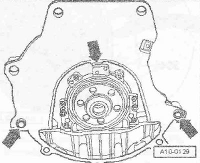
Release screws on engine mounting -arrows-.
Remove the power unit forward. If necessary, disconnect gearbox from engine.
Engine installation
Install in reverse order, paying attention to the following: When installing, replace self-locking nuts and bolts. Replace bolts tightened to a certain angle, as well as cuffs and gaskets. The hoses and pipes of the air pressurization system must be cleaned of oils and grease before installation. Never use lubricants. Use an XCV of the appropriate series to fasten all hose connections. When assembling, install all binders in their original places. Clean input shaft ring gear and used clutch disc hub ring gear, remove any corrosion and apply a thin coat of clutch disc hub ring gear grease -G 000 100- to the input shaft ring gear. Do not lubricate the guide bushing. If necessary, check the centering of the clutch disc. Check the clutch release bearing for wear, replace if necessary. Check the presence of centering bushings for the power unit in the cylinder block, insert bushings if necessary.
Position seal on dowel sleeves -arrows-. When installing the power unit, take into account the access to the gear selector and pre-catalyst. Install the engine mount bracket. Install the gearbox mounting hardware. Install the fuel unit. Install the engine mount. Install pre-catalyst with main catalytic converter. Install the clutch slave cylinder. Install the gear selector. Install drive shafts. Install the stabilizer links. Install the carrier arm. Install bumper. Install fenders. Electrical connections and wiring. Observe precautions when disconnecting battery terminals. Do not use the charger to start the engine. There is a risk of damage to the vehicle control units. Install and adjust wiper arms. Check oil level. Fill up the coolant. Perform basic MCP setup.
Tightening torques
Instruction. The tightening torques given are valid for lightly oiled, phosphated or oxidized nuts and bolts. It is allowed to use additional lubricants, such as motor or transmission oils, except for those containing graphite. Do not use parts without lubrication. Torque tolerance is±15%.
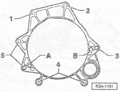
Engine/Gearbox Mount
| 1, 2 | N12x60 | 80 |
| 3 | N12x80 | 80 |
| 4 | N10x50 | 45 |
| 5 | N12x180 | 80 |
| a, b | Centering bushes | |
| Bolts/nuts M6 | 9 |
| M8 | 20 |
| M10 | 40 |
| N12 | 65 |
| Heat shield in the drive hall to the gearbox | 23 |
| air duct | 8 |
Visitor comments