
Table of contents: Removal ↓ Installation ↓
Removal
Before disconnecting the battery, find out if you have a radio activation code.
Turn off the ignition and disconnect the ground wire from the battery.
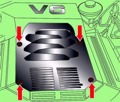
Fig. 3.1–41. Location of engine casing mounting screws
Unscrew the four screws and remove the engine cover (see Fig. 3.1–41).
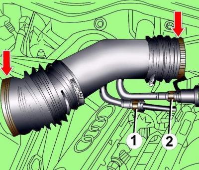
Fig. 3.1–42. Location of the clamps for fastening the air flow meter air pipe and the intake pipe: 1 – fuel supply pipe; 2 – fuel supply hose
Loosen the clamps and remove the air pipe connecting the air flow meter and the suction pipe (see Fig. 3.1–42).
Disconnect the lambda sensor electrical connector from the right side of the engine compartment, remove the connector half from the bracket and move it down with the wire.
Disconnect the lambda sensor electrical connector from the left side of the engine compartment, remove the connector half from the bracket and move it down with the wire.
Unscrew the nuts securing the left and right exhaust pipes, accessible from above.
Cars with cruise control system
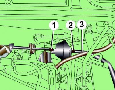
Fig. 9–12. Location of control rod (1), vacuum block mounting nut (2) and vacuum hose (3)
Disconnect control rod 1 (Fig. 9–12) from the vacuum block.
Remove vacuum hose 3 from the vacuum block.
Unscrew nut 2 and remove the vacuum block.
All models
Disconnect the electrical connector from the spark plug of the fifth cylinder.
Disconnect the electrical connector from the coolant temperature sensor G2.
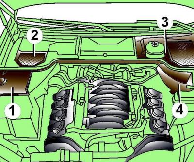
Fig. 9–13. Location of protective covers (1–4) in the rear of the engine compartment
Remove the protective covers at the rear of the engine compartment (Fig. 9–13).
Prepare the left 10-222A/4 adapter and the 10-222A lifting device with clamps to support the engine.
Install the 10-222A/4 adapter and 10-222A lifting device on the posts and connect them together.
Secure the lifting device clamp to the engine.
By turning the screw of the lifting device, tighten the clamp so that the weight of the engine is supported by the lifting device.
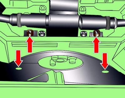
Fig. 9–14. Location of the screws for fastening the poly V-belt cover
Unscrew the screws and remove the poly V-belt cover (Fig. 9–14).
Warning: Use chalk, marker or paint to mark the direction of rotation of the poly V-belt. If the poly V-belt rotates in the opposite direction during installation, it will cause damage to the belt.
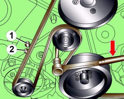
Fig. 9–15. Loosening the tension of the poly V-belt: 1, 2 – locations of pins for fixing the tensioning mechanism
Using a 10 mm Allen key, loosen the tension on the poly V-belt by turning the tensioning mechanism clockwise until holes 1 and 2 are aligned (Fig. 9–15).
In Fig. 9–15, the arrow shows the direction of rotation of the Allen key to reduce the tension of the poly V-belt.
Fix the tensioning mechanism in this position by inserting a 5 mm diameter steel rod into the hole.
Remove the poly V-belt from the pulleys.
Remove the front pulleys.
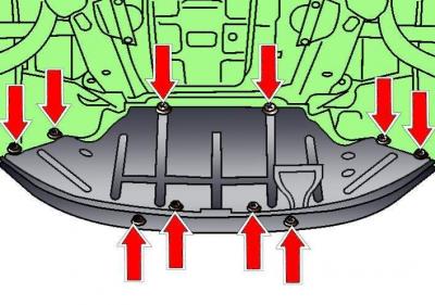
Fig. 3.1–1. Location of the engine compartment lower mudguard mounting fasteners
Release the fasteners and remove the lower engine compartment splash guard (see Fig. 3.1–1).
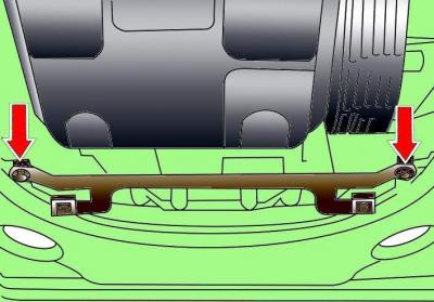
Fig. 3.1–2. Location of engine compartment lower mudguard bracket mounting bolts
Unscrew the two bolts and remove the engine compartment lower mudguard bracket (see Fig. 3.1–2).
Disconnect the air duct mount from the generator.
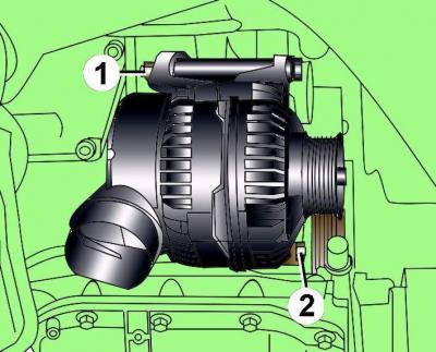
Fig. 9–16. Location of the nut (1) and bolt (2) for fastening the generator
Unscrew nut 1 and bolt 2 securing the generator (Fig. 9–16).
Move generator to the side, disconnect the wires from it and remove generator.
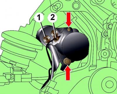
Fig. 9–17. Location of starter mounting bolts: 1 – nut; 2 – electrical connector
Disconnect the electrical connector from the starter, then unscrew nut 1 (Fig. 9–17) and disconnect the positive wire from the starter.
Unscrew the two bolts shown by the arrows in Fig. 9–17 that secure the starter and carefully remove the starter.
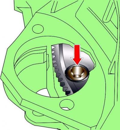
Fig. 9–18. Location of torque converter mounting bolt
Through the hole that opens after removing the starter, unscrew the three torque converter mounting bolts (Fig. 9–18). To access each subsequent bolt, it is necessary to turn the engine crankshaft in the direction of its working rotation by 1/3 of a turn. The crankshaft must be turned using the central crankshaft pulley mounting bolt.
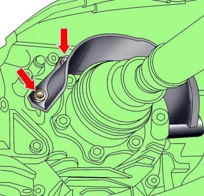
Fig. 9–19. Location of drive shaft heat shield mounting bolts
Unscrew and remove the heat shields of the right and left drive shafts (Fig. 9–19).
Unscrew the drive shafts from the gearbox flanges.
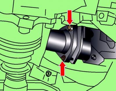
Fig. 9–20. Location of nuts securing the exhaust inlet pipe to the front muffler
From underneath the vehicle, unscrew the nuts securing the exhaust inlet pipe to the front muffler (Fig. 9–20).
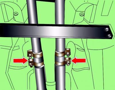
Fig. 9–21. Location of the exhaust system coupling fastening nuts
Unscrew the nuts (Fig. 9–21) securing the connecting sleeves of the exhaust system pipes.
Carefully remove the front exhaust pipe with the catalytic converter and lambda sensors. Do not damage the wires going to the lambda sensors.
Unscrew the mounting bolts and remove the heat shield located behind the gearbox.
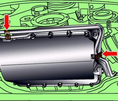
Fig. 9–22. Location of bolts for fastening the brackets supporting the pipes to the automatic transmission
Remove the two bolts (Fig. 9–22) securing the pipe support brackets to the automatic transmission.
Remove the three bolts securing the lower part of the gearbox to the engine.
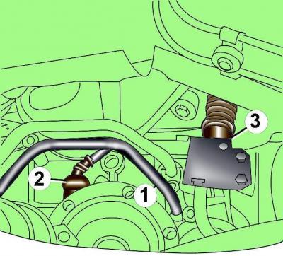
Fig. 9–23. Location of the pipe mounting bolt (1), G38 acceleration sensor (2) and multifunction switch (3) connectors of the automatic transmission
Unscrew the bolt securing the pipes to the gearbox, move the pipes to the side and close the open ends of the pipes with plugs (Fig. 9–23).
Disconnect the electrical connector of the acceleration sensor G38 and the multifunction switch from the automatic transmission (see Fig. 9-23).
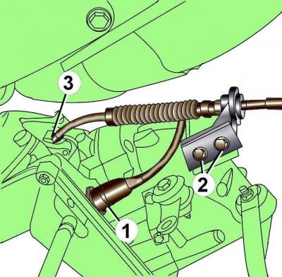
Fig. 9–24. Location of the 8-pin electrical connector (1), bracket mounting bolts (2), and selector cable mounting bolt (3) to the automatic transmission
Remove the retainer, turn clockwise and disconnect the 8-pin electrical connector from the transmission (Fig. 9-24).
Unscrew bolts 2 and remove the selector cable bracket from the automatic transmission.
Unscrew the nut, remove the washer and, by pulling, remove the selector cable from the automatic transmission control lever.
Release the wires from the clamps on the gearbox.
Attach a special device to a stationary jack, install it under the gearbox and raise the jack so that the weight of the gearbox is supported by the jack.
If you do not have special tools for removing the gearbox, support the gearbox with a jack using a wooden block.
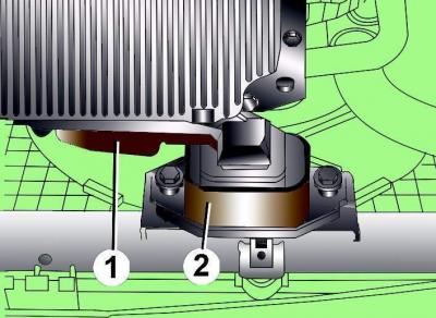
Fig. 9–25. Location of the engine torque compensator support: 1 – support; 2 – limiter
Unscrew the mounting bolts of support 1 (Fig. 9–25) of the engine torque compensator and, moving the support, remove it.
Unscrew the bolts and remove the left and right gearbox supports.
Unscrew the transmission mounting bolts to the rear of the lower frame. The lower frame should be 80 mm below the body. If necessary, partially unscrew the lower frame bracket mounting bolts.
Carefully lower the rear of the transmission slightly.
Move the drive shafts forward and tie them to the body with soft wire.
While supporting the front of the transmission, remove the upper transmission-to-engine mounting bolts.
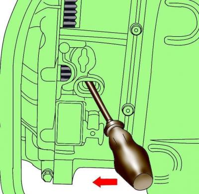
Fig. 9–26. Using a pry bar to hold the torque converter against the engine when removing an automatic transmission
Move the gearbox away from the engine, pressing the torque converter against the engine with a crowbar (Fig. 9–26).
Carefully lower the transmission and remove it from under the vehicle.
Secure the torque converter to the engine.
Installation
Installation is carried out in the reverse order of removal, taking into account the following.
When installing the engine, it is necessary to replace the self-locking nuts and bolts, which were tightened by turning them to a certain angle, with new ones, as well as the sealing rings and gaskets.
When installing, check for the presence of centering bushings that determine the relative position of the engine and gearbox.
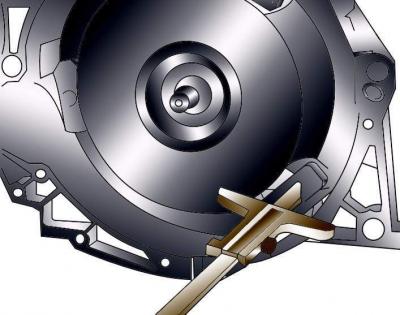
Fig. 9–27. Measuring the distance between the bearing surface for the torque converter mounting bolts and the bearing surface of the crankcase
Check the correct installation of the torque converter. If the distance between the supporting surface for the torque converter mounting bolts and the crankcase surface is 19 mm, then the torque converter is installed correctly. If the torque converter is installed incorrectly, this distance is about 14 mm (Fig. 9-27). If the torque converter is installed incorrectly, its leading part and the automatic transmission pump are destroyed.
Make sure that no pipes, wires or electrical connectors are pinched when installing the transmission.
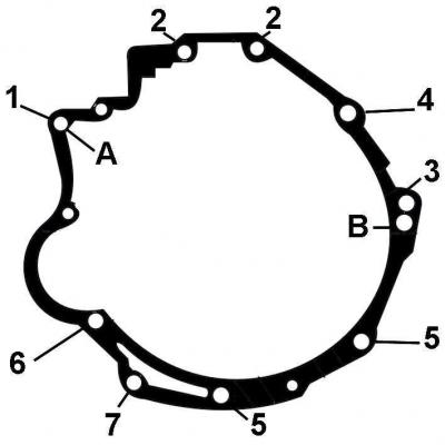
Fig. 9–28. Location and numbering of bolts for fastening the automatic transmission to the engine: A, B – locations for installing centering bushings
| Position | Bolt | Number of bolts | Tightening torque, Nm |
| 1 | M12x50 | 1 | 65 |
| 2 | M12x67 | 2 | 65 |
| 3 | M12x80 | 2 | 65 |
| 4 | M12x100 | 1 | 65 |
| 5 | M10x38 | 2 | 45 |
| 6 | M10x80 | 1 | 45 |
| 7 | M8x40 | 1 | 20 |
Install and tighten the gearbox-to-engine mounting bolts (Fig. 9–28).
When connecting the tubes to the gearbox, it is necessary to use new sealing rings, having previously lubricated them with a thin layer of technical petroleum jelly.
Replace the M14 bolts securing the gearbox to the lower frame.
Check the installation of the selector cable.
Make sure the exhaust system is properly mounted on the suspension and does not touch the body when rocking.
Check the automatic transmission oil level.
Check that the electrical connectors are connected correctly.
Connect the ground wire to the battery.
Turn on radio and enter the code into it.
Raise the power windows all the way up, then press all power window switches again for at least 1 second to the closed position to activate the power window control unit.
Set the time on the clock.