
Table of contents: Removal ↓ Electrically adjustable seat with… ↓ Installation ↓ Electrically adjustable seat with… ↓ Manually adjustable seat ↓
Removal
To remove the seat, you need the AUDI VAS-5061 airbag adapter/device. The adapter prevents the airbag from deploying when the seat is removed.
Power seat with memory. Fully recline up and back.
Attention
- Disconnect the battery ground (-) cable with the ignition off.
- When disconnecting the wires from the battery terminals, the memory units of the control units erase the data on the recorded faults, so before disconnecting the wires, you must contact a workshop to recall the faults recorded in the memory. After connecting the wires to the battery terminals, it is necessary to activate and reprogram the electric windows, as well as the position of the rear-view mirrors and seats.
- If the car has a radio receiver with a code, then before disconnecting the wires from the terminals from the battery, check that there is a code to reactivate the receiver. Otherwise, the radio receiver can only be put into operation at a specialized station.
Move the manual seat forward.
Remove the seat guide cover from the door side. To do this, pry it off with your finger in the direction of arrow A (fig. 12.97) cover 1 and press the locking lug 2 in the direction of arrow B. In this position, pull cover 1 back with force.
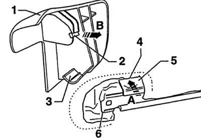
Fig. 12.97. Removing the protective cover of the seat guides from the door side
1 - casing,
2 - locking protrusion,
3 - tongue,
4 - guide,
5 - sheet steel overlay,
6 - sleds.
Remove the protective cover from the inside. Remove the protective cover of the seat guides from the door side. To do this, pry it off with your finger in the direction of arrow A (fig. 12.98) cover 1 and press the locking tab 2 in the direction of arrow B. In this position, push cover 1 downwards and pull it back.
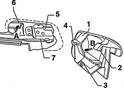
Fig. 12.98. Removing the protective cover of the seat guides from the inside
1 - casing,
2 - locking protrusion,
3 - retainer,
4 - tongue,
5 - guide.
Recline the manual seat.
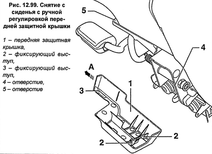
Manually adjustable seat. Remove the front protective cover from the seat 1 (fig. 12.99). To do this, pull the cover slightly upwards until the locking protrusions 3 come out of the hole 4. Fold the top of the cover forward, the locking protrusion 2 at the bottom of the cover will come out of the groove.
Electrically adjustable seat with memory
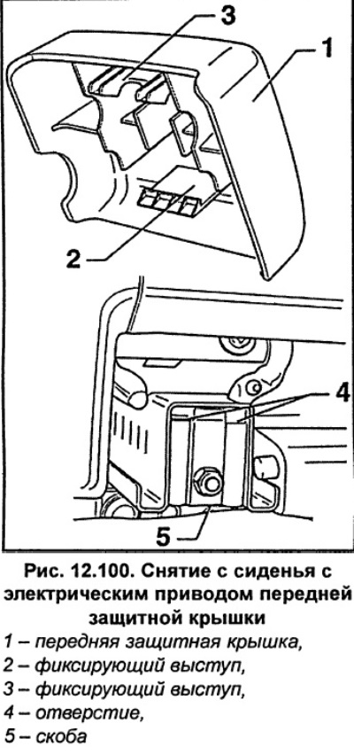
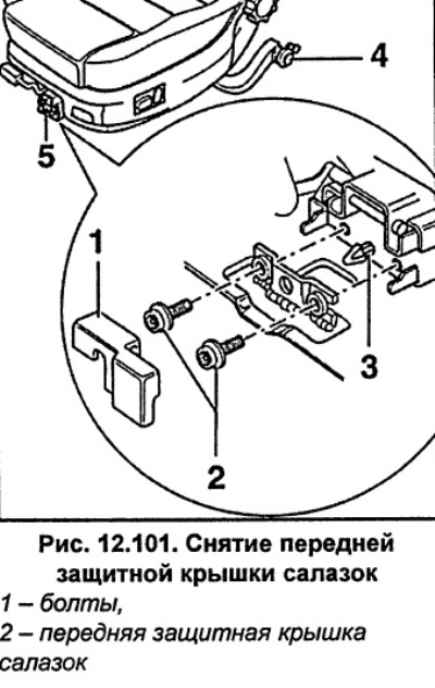
Remove the front protective cover from the seat 1 (fig. 12.100). To do this, pull the cover slightly upwards until the locking protrusions 3 come out of the hole 4. Fold the top of the cover forward, the locking protrusion 2 at the bottom of the cover will come out of the groove.
Unscrew bolts 2 (fig. 12.101). Pull the seat forwards out of the clamp 3.
Safety Notice
- Disconnect the wires from the side airbag and connect the VAS 5061 airbag adapter.
- To prevent unexpected airbag deployment, it is important to discharge any possible electrostatic charge before disconnecting and reconnecting the airbag electrical connector.
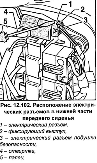
Disconnect the airbag electrical connector 1 (fig. 12.102) from the socket at the bottom of the seat. To do this, pry the electrical connector out of the retaining lug 2 with a screwdriver 4. If the electrical connector cannot be removed in this way, press the retaining lug 5 of the side airbag with your finger and at the same time pull the airbag connector forward with your other hand.
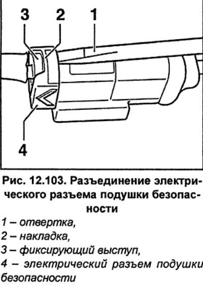
Pry it up with a screwdriver 1 (fig. 12.103) cover 2 over the retaining lug 3 and disconnect the airbag electrical connector 4.
Insert connector 2 (fig. 12.104) adapter into the socket 5.
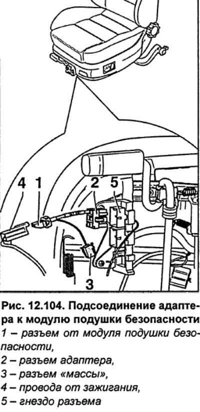
Connect the ignition wires 4 from the airbag module to the connector 1 of the airbag adapter. In order for the airbag ground circuit to be complete when disassembled, the airbag adapter must remain connected to the seat at all times until the seat is reassembled and connected.
If necessary, disconnect the seat heating electrical connector.
Move the floor mat in the area of the guide bar.
Slide the seat back and remove it from the guide bar.
Installation
From the rear, insert the seat into the guide bar so that the front sliding element 5 (fig. 12.101) and the rear roller 4 of the seat completely entered the guide bar.
If longitudinal adjustment of the seat is difficult, lubricate the sliding elements with multi-purpose grease (see fig. 12.101).
If necessary, connect the electrical connector for the seat heater.
To prevent unexpected airbag deployment, it is important to discharge any possible electrostatic charge before disconnecting and reconnecting the airbag electrical connector.
Disconnect the airbag adapter. Connect the side airbag electrical connector. Make sure that the jumper on the connector is on top.
Insert clamp 3 (fig. 12.101) and tighten bolt 2 to 23 Nm.
Electrically adjustable seat with memory
Install the front protective cover 1 (fig. 12.100) on the seat. To do this, insert the locking lug of the casing 2 into the bracket 5. Press the cover with the fastening clamps 2 to the seat 4.
Manually adjustable seat
Install the front protective cover 1 (fig. 12.99) on the seat. To do this, insert the locking lug of the casing 3 into the bracket 5. Press the cover with the fastening clamps 2 to the seat 4.
Install the protective cover of the seat guides from the inside. To do this, install the cover, press on the floor mat and simultaneously slide it forward so that the locking tabs 2 and 3 (fig. 12.98) entered holes 6 and 7.
Place the protective cover on the door side. To do this, install the cover so that the guide 3 (fig. 12.97) lay under the steel sheet overlay 6, and the locking protrusion 2 was located under the seat bar 5.
Finally, press the cover's floor mat and simultaneously move it forward until the locking tab 2 (fig. 12.97) will not fit into hole 4.
Connect the ground wire to the battery. Repeat the steps to memorize the position of the seats, mirrors, etc., and also set the time on the clock and enter the code into the radio.
If the airbag warning light shows an error after installation, you must contact the workshop.
[The original version of the article is posted on the website: AudiManual.ru]