
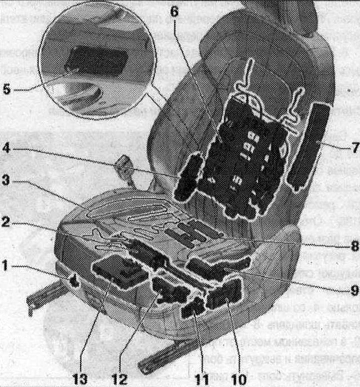
 1. Seat position sensor. Driver's side: Driver seat position sensor -G553-. On the front passenger side: front passenger seat position sensor -G554-; 2. Electric motor for adjusting the longitudinal position of the seat. Driver's side: driver's seat longitudinal lumbar adjustment motor -V28-. On the front passenger side: front passenger seat fore/aft adjustment motor -V31-; 3. Heating element; 4. Backrest adjustment motor. Driver's side: Driver's seat backrest adjustment motor -V45-. On the front passenger side: front passenger seat backrest adjustment motor -V46-; 5. Footwell lamp; 6. Four-way lumbar support. Doesn't understand; Available only assembled. Driver's side: with driver's seat longitudinal lumbar adjustment motor -V125-. With motor for driver's seat lumbar support height adjustment -V129-. Front passenger side: Front passenger seat longitudinal lumbar adjustment motor -V126-. Front passenger seat lumbar support height adjustment motor -V130-; 7. Side Airbag, front. Driver's side: with driver's side Airbag squib -N199-; on the front passenger side: with front passenger side Airbag squib -N200-; 8. Seat occupied sensor, front passenger side -G128- (only for front passenger seat); 9. Electric motor for seat height adjustment. Driver's side: Driver's seat height adjustment motor -V245-. On the front passenger side: Front passenger seat height adjustment motor -V246- 10. Seat position control panel. Driver's side: Driver's seat position control unit -E470- with: switch for adjusting the driver's seat backrest -E96-; Driver's seat tilt adjustment switch -E222-; Driver's seat longitudinal adjustment switch -E363-; switch for height adjustment of the driver's seat -E364-. On the front passenger side: front passenger seat position control unit -E471- with: front passenger seat longitudinal adjustment switch -E64-; switch for adjusting the backrest of the front passenger seat -E98-; button for adjusting the angle of the front passenger seat -E334-; switch for height adjustment of front passenger seat -E365-; 11. Lumbar support adjustment switch. Driver's side: driver's seat lumbar support adjustment switch -E176-. On the front passenger side: front passenger seat lumbar support adjustment switch -E177-; 12. Seat tilt adjustment motor. Driver's side: Driver's seat cushion angle adjustment motor -V243-. On the front passenger side: front passenger seat cushion angle adjustment motor -V244-; 13. Used for adjusting the position of the seat and steering column with memory function. Option to equip the seat with a memory function: On the driver's side, control unit for seat and steering column adjustment with memory function -J136-; On the front passenger side - front passenger seat adjustment control unit with memory function -J521-. Set option with seat heating or comfort seat: driver's side - front left seat ventilation control unit -J800- (Built-in seat heating function); Front passenger side - Right front seat ventilation control unit -J799- (Built-in seat heating function);
Removing the backrest adjustment motor
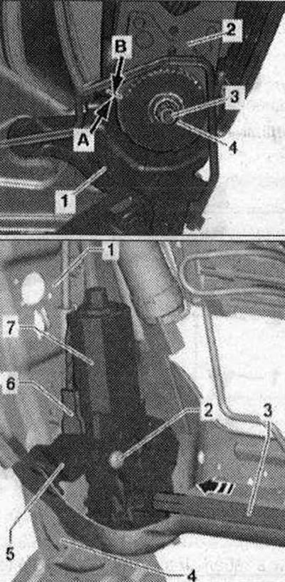
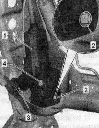
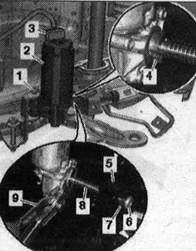
Remove the front seat. Attach front seat to seat repair holder -VAS 6136-. Remove the cover from the tunnel side. Remove the trim from the threshold side. Remove the backrest pad. Mark the angular position of the backrest upholstery on the left and right, as shown in the figure: apply indelible marking (hatch) -arrow B- on the backrest frame -2- directly on the front edge -arrow A- of the upholstery -1-.
When marking, avoid damaging the surface of the pad by scratching or damaging markings. Unscrew the nut -4- of the shaft -3-. Remove the cushions from the backrest frame in the area of the frame upholstery. Remove the shaft -3- -in the direction of the arrow- from the backrest frame -1-. Disconnect plug connector -6- from seat back adjustment motor -7-. Unscrew the screw -2- and remove the electric motor for adjusting the backrest position from the bracket -5-, to slightly press the electric motor for adjusting the lumbar support forward
Installation
Before installation, clean the shaft thread -3-, for example with a tap. Check the position of the frame -2- and upholstery -1- on the left and right side of the backrest. The backrest frame on the left and right must be in the position marked before removal -arrows A and B-. If the backrest frame on the left and right is not in the position marked before removal, correct its position. Install the backrest adjustment motor -1- onto the bracket -3-. Replace bolt -4-, coat it with thread varnish -D OOO 600 A2- and tighten by hand.
Do not move the backrest adjustment motor yet. Slide the shaft through the cover first (from the tunnel side) to the mounting -2- in the backrest adjustment motor. Check that the profiles of the displaced shaft and the mounting -2- in the electric backrest adjustment motor match each other.
The profiles of the shaft and the mounting in the backrest adjustment motor match each other: move the shaft through the mounting in the backrest adjustment motor until it stops (from the threshold).
Shaft profiles and mountings in the backrest adjustment motor do not match each other: Apply voltage (12 Volt) from additional power source to the backrest adjustment motor -1 -. Rotate the fastening -2- until the profiles of the shaft and fastening coincide with each other. Move the shaft through the mount in the backrest adjustment motor until it stops (from the threshold).
Apply thread varnish -D OOO 600 A2- to the shaft thread. Screw a new nut -4- onto the shaft -3- and tighten. Tighten the bolts of the backrest adjustment motor on the bracket -3- to the specified tightening torque. Install in reverse order. At the same time, take into account that el. The connectors must be inserted all the way until they click into place. Connect the battery ground cable with the ignition on.
Electric seat height adjustment motor
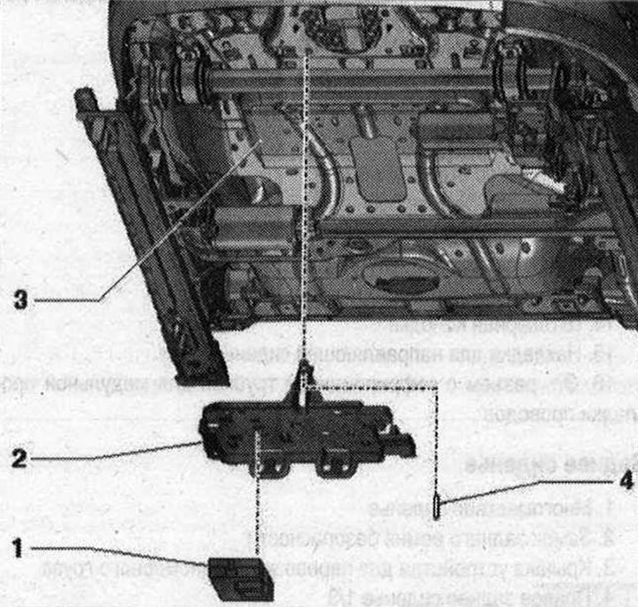
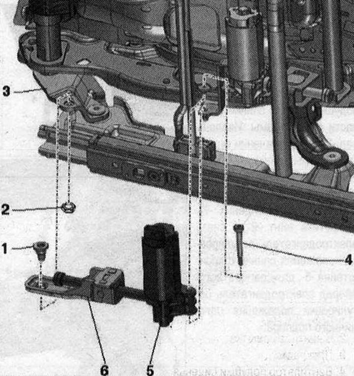 1. Bolt. Self-locking. 18 Nm. Replace after each removal. The threaded hole for the bolt should be cleaned, for example, using a tap; 2. Nut (depending on design). 14 Nm; 3. Seat base; 4. Bolt. Self-locking. 8 Nm. Replace after each removal. Follow the instructions when removing and installing. The threaded hole for the bolt should be cleaned, for example, using a tap; 5. Electric motor for seat height adjustment. Driver's side: Driver's seat height adjustment motor -V245-. On the front passenger side: front passenger seat height adjustment motor -V246-; 6. Spindle nut, part of the electric motor for adjusting the seat height. If the threads in the spindle nut are damaged, the mounting part must be replaced;
Removing the seat tilt motor
Move the front seat all the way up. Remove the front seat. Attach the front seat to the seat repair holder -VAS 6136-. Disconnect plug connectors -3- for seat cushion angle adjustment motor. Using a screwdriver, remove the retaining ring -4- from the spindle. Hold the spindle -8- with pliers -9- in the shown location from turning and unscrew the bolt -6-. Unscrew the bolt -1- and remove the electric motor for adjusting the seat cushion angle -2- from the bracket. Press the upper and lower frames of the seat recess away from each other, tilt the electric motor for adjusting the angle of the seat cushion forward using the lead screw and unscrew it from the lead screw nut -5-.
Installation
Screw the drive spindle -8- as far as possible into the spindle nut -5-. Screw the bolt -6- into the lead screw by hand. Tightening the bolt -6- to the prescribed torque is possible if the seat is in the vehicle and connected to the on-board power supply. Installation is in reverse order, taking into account that el. The connectors must be inserted all the way until they click into place. Connect the battery ground cable with the ignition on. The seat is located in the vehicle and is connected to the on-board network. Move the seat downwards using the tilt adjustment and tighten the bolt -6- at the same time.
Control panel and seat adjustment switch
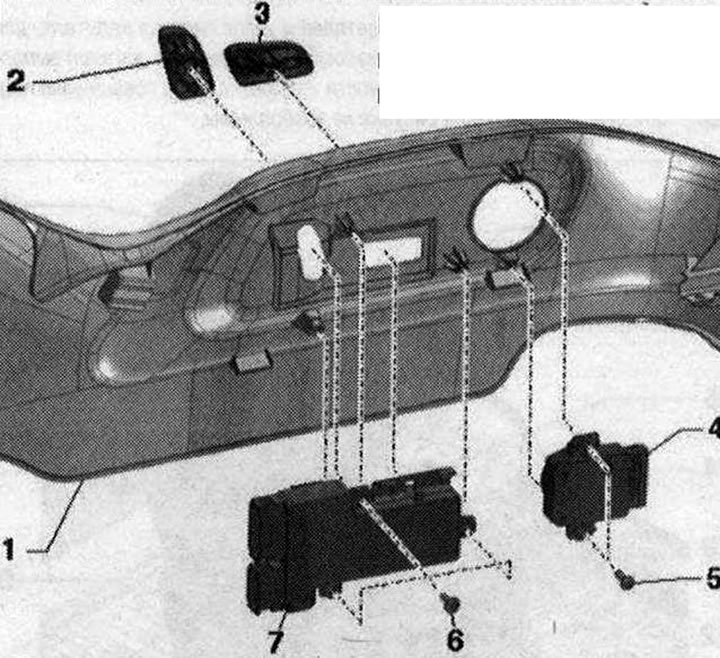 1. Threshold side trim; 2. Seat back adjustment control mechanism. Attached to the control panel; 3. Seat position lever. Attached to the control panel; 4. Lumbar support adjustment switch. Driver's side: driver's seat lumbar support adjustment switch -E176-; On the front passenger side: lumbar support adjustment switch for the front passenger seat -E177-. The switch cannot be separated from the control button; 5. Bolt. 2 pcs. 1.3 Nm; 6. Bolt. 3 pcs. 1.3 N'M; 7. Seat position control panel. Driver's side: driver's seat position control panel -E470-; switch for adjusting the driver's seat backrest -E96-; Driver's seat tilt adjustment switch -E222-; Driver's seat longitudinal adjustment switch -E363-; switch for height adjustment of the driver's seat -E364-. On the front passenger side: front passenger seat position control panel -E471-; Switch for front passenger seat longitudinal adjustment -E64-; switch for adjusting the backrest of the front passenger seat -E98-; button for adjusting the angle of the front passenger seat -E334-; Switch for height adjustment of front passenger seat -E365-
Seat ventilation control unit (seat with heating function)
 1. Used seat ventilation (seat with heating function). Driver's side: Front left seat ventilation control unit -J800-. Front passenger side: Front right seat ventilation control unit -J799-. Connected with bracket; 2. Bracket; 3. Front seat; 4. Pin for attaching the bracket to the seat cushion;
Installation diagram for seat cushion and backrest fan
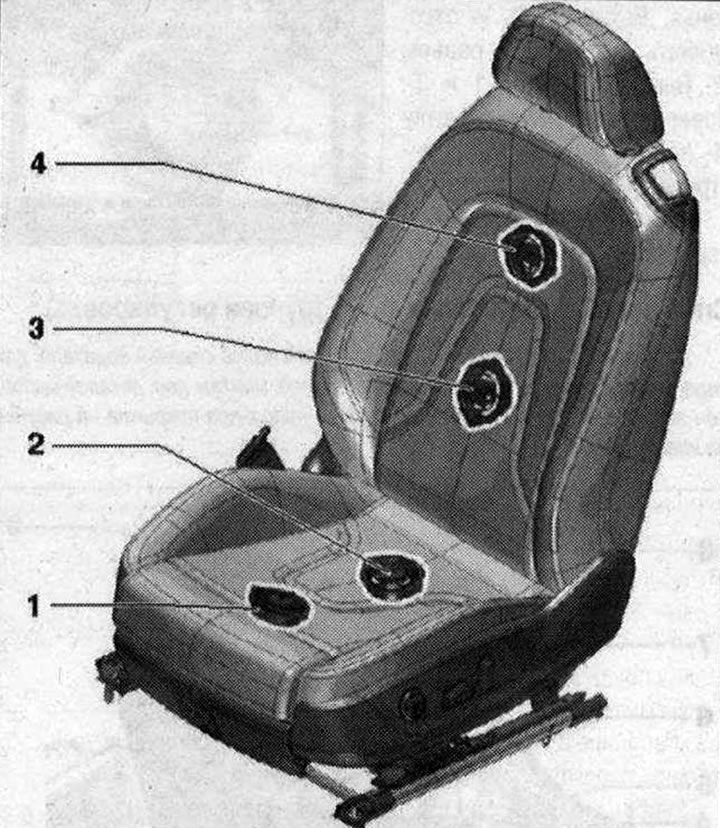 1. Seat cushion fan. Driver's side: Driver's seat cushion fan -V390-. On the front passenger side: front passenger seat cushion fan -V391-; 2. Fan 2 seat cushions. Driver's side: Driver seat cushion fan 2 -V419-. On the front passenger side: front passenger seat cushion fan 2 -V420-; 3. Fan 2 seat backs. Driver's side: Driver seat backrest fan 2 -V417-. On the front passenger side: front passenger seat backrest fan 2 -V418-; 4. Seat back fan. Driver's side: Driver's seatback fan -V388-. On the front passenger side: front passenger seatback fan -V389-
Seat cushion fan
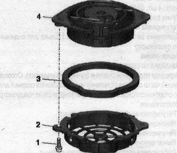 1. Bolt. 1.5 Nm; 2. Protective grille; 3. Gasket; 4. Seat cushion fan
Removal
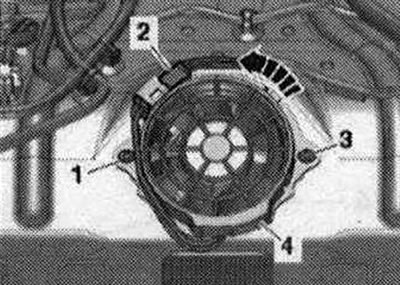
Remove the seat cushion cover. Release and disconnect plug connector -2-. Remove bolts -1 - and -3-. Turn the protective grille -4- counterclockwise -arrow- and remove the fan.
Install in reverse order.
Visitor comments