
Table of contents: Removal the front seat if the seat… ↓ Check the seat longitudinal… ↓ Removal the seat if the electric… ↓ Removal in case of faulty control… ↓ Installation ↓ Threshold side trim ↓ Removal the trim from the threshold… ↓ Installation ↓
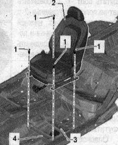
Note. The description of the driver's seat parts and units is given, for the front passenger seat it is similar, the installation of additional parts is performed in mirror image. For greater clarity, the four-way lumbar support and floor covering are not shown in the figure.
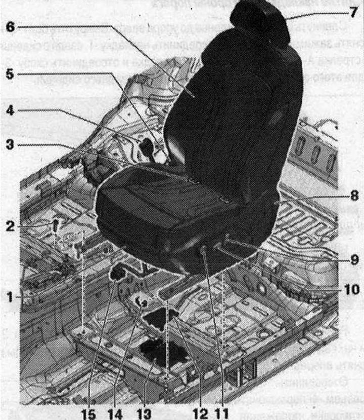 1. Storage compartment; 2. Bolt. 4 pcs. 50 Nm; 3. ISOFIX child seat mountings (for front passenger seat only). Post-accident inspection; 4. Belt lock; 5. Tunnel side overlay; 6. Standard front seat (electrically adjustable); 7. Headrest; 8. Overlay on the threshold side; 9. Lever; 10. Lever. Switch for adjusting the longitudinal position, backrest angle, seat height; 11. Lumbar support lever; 12. Connection module overlay; 13. Plug-in connector; 14. Seat guide cover. 4 pcs.; 15. Electrical connector with corrugated tube for modular wiring;
Removal the front seat if the seat longitudinal adjustment motor is faulty or the control unit is faulty
Check the seat longitudinal adjustment or control unit
Move the seat all the way up. Before removing the seats again, check the electrical and electronic components and lines to avoid unnecessary repair costs. Perform the following checks: Check the fuse. Check the voltage at the connection module, if necessary, perform a fault finding. Check the voltage at the control unit. Check the voltage at the seat longitudinal adjustment motor "V288". If the fuse is defective, replace it. If there is no voltage at the switch unit: repair the wiring or replace it. If the driver's seat longitudinal adjustment motor "V28" or the front passenger seat longitudinal adjustment motor "V31" is defective: replace the seat cushion frame. If the seat and steering column adjustment control unit with memory "J136" or the front passenger seat adjustment control unit with memory "J521" is defective: replace the control unit.
Removal the seat if the electric motor for adjusting the longitudinal position of the seat is faulty
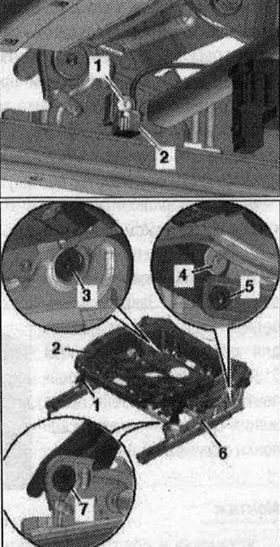
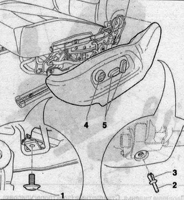
Turn on the ignition. Disconnect the battery ground cable with the ignition on. Disconnect the connectors of the connection module. Connect the Airbag adapter -VAS 6281. Unscrew bolt "1". Disconnect the seat position sensor "2" with the electrical wire from the lower frame of the seat base and put it aside. Disconnect the electrical connector of the front seat belt buckle.
Disconnect the plug connector from the seat longitudinal adjustment motor. Unscrew bolt "5", to do this, first unscrew the lock nut.
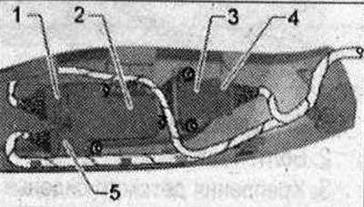
Risk of damage to threaded holes or bushings at support points (threaded connection of the upper and lower frames). To remove the bolts listed below, the 2nd mechanic should lightly press the seat down by the backrest. Unscrew bolts "1,3,4,7". Lift the upper frame of the seat base "2-2" with the mechanic from the lower frame "6" and remove it from the car.
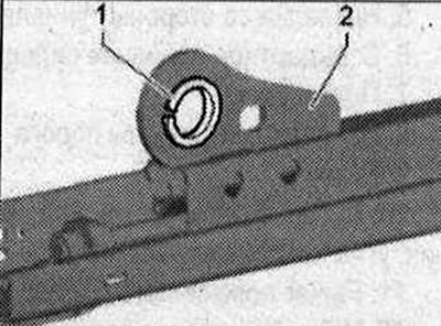
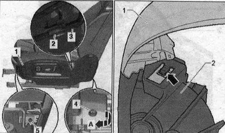
The picture shows the seat recess without cushions, upholstery and backrest. Make sure that bushings "1" in the support points (threaded connection of the upper and lower frames) "2" were not damaged. It is not possible to replace the bushings using workshop equipment. If the bushings are damaged, the corresponding mounting part must be replaced. Unscrew the accessible bolts of the seat guides on the console. Remove the faulty seat longitudinal adjustment motor "1" from the bracket "arrow A". Unscrew the screws "arrow B" and remove the crossbar "3" of the seat guides. Unscrew the bolts "arrow C" and remove the bracket "2" of the seat longitudinal adjustment motor.
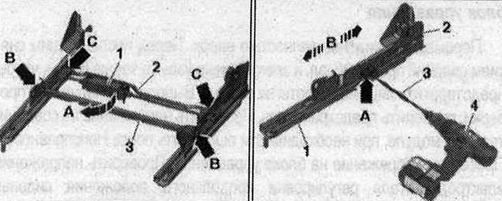
Clamp the drive shaft "3" of the electric motor for adjusting the longitudinal position of the seat in the screwdriver for AKM "4" or a drill. Insert the drive shaft into the drive spindle "arrow A" and rotate the seat guide "2" "arrow B" forward/backward until the bolt of the lower seat guide "1" is accessible.
Loosen the bolt and remove the seat guide. Repeat these operations on the opposite side. Replace the lower seat base frame with the longitudinal seat adjustment motor.
Removal in case of faulty control unit for adjusting the position of the seat and steering column with memory function
Turn on the ignition. Disconnect the battery ground cable with the ignition on. Disconnect the plug from the seat longitudinal adjustment motor. Connect the seat longitudinal adjustment motor using an external power source and move the seat forward or backward so that bolts "1" (4 pieces) become visible.
Remove the screws. Disconnect the connectors of the connection module. Connect the Airbag adapter "VAS 6281". Remove the front seat from the car with the help of a second mechanic. Secure the front seat in the seat repair holder "VAS 6136". Turn the control unit to adjust the position of the seat and steering column with memory function.
Installation
Installation in reverse order: remove the Airbag adapter "VAS 6281" only after installing the front seat. Insert the plugs into the connectors of the connection module in the bottom of the car. Note that the electrical connectors must be inserted until they stop with an audible lock. Connect the battery ground cable with the ignition on.
Threshold side trim
Removing the trim from the threshold side. Removal can be done with the seat installed.
 1. Bolt 8 Nm; 2. Clamping pin; 3. Expansion clamp; 4. Lumbar support adjustment switch; 5. Seat position control panel.
Removal the trim from the threshold side
Move the front seat all the way up. Unscrew bolt "5" and remove clamp "4" of the pad. Disconnect pad -1. from the rear of the seat "arrow A". Open clamp "2" to the pad and disconnect bracket "3". To do this, carefully pull the pad off the front seat.
Release the fasteners "arrow" connecting the glove pocket "2" and the trim on the threshold side "1". Disconnect the trim from the bracket and remove it forward.
Disconnect plug connector "4" of lumbar support adjustment switch "3". Disconnect plug connectors "1, 5" of seat position control panel "2".
Remove the trim from the threshold side.
Installation
Installation in reverse order, taking into account that the electrical connectors must be inserted until they stop with an audible lock. Ensure that the trim is correctly fixed on the threshold side with a clamp and that the clamps are closed. Ensure that the wires are located as close as possible to the plug connectors "1,4,5".
(The original source of the article can be found on the website: «AUDImanual.ru»)